Sets parameters for calculation of a beam.
|
Access: |
Ribbon: Design tab  Frame panel Beam/Column Calculator Frame panel Beam/Column Calculator |
Loads & Supports
Use this area to specify loads and supports. Select Loads or Supports from the drop-down list. Depending on your selection, the commands within the toolbar display. The Options button is always available.
Click the button to add appropriate force, load, or support. A dialog box displays where you can edit the values.
Selected force or support displays in the list where you can edit or delete it.
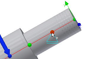
The graphical representation of loads and supports is displayed in Autodesk Inventor window. Work with the preview as with 3D Grips. You can drag the preview to the appropriate position. Double-click to display the edit dialog. Move the mouse cursor above the graphical representations to display a description of a force or support. When you select load or support in the list in the Beam Calculation tab, its graphical representation is selected within the Autodesk Inventor window, and vice versa.
Only one support carries the axial load, and its diagrammatic display is different from others.
|
Loads |
|
|
|
Add Force Opens the Radial Force dialog where you can set the radial force properties, such as distance or angle. |
|
|
Add Axial Force Click to open the Axial Force dialog window where you can set the axial force properties, such as distance or axial force value. |
|
|
Add Continuous Load Click to open the Continuous Load dialog box and set the continuous load properties, such as length or angle. |
|
|
Add Bending Moment Specifies moments in all directions. M x (torque), M y (bending - XZ plane) and M z (bending - XY plane). Positive moment actuates in the counterclockwise direction. Click to open the Bending Moment dialog box and set the bending moment properties. |
|
|
Add Torque Torque is entered using two forces which are mutually opposite. One of the forces represents the actual torque, the second force must be negative (for example, 150 Nm and -150 Nm). The sum of all torques (Max) must equal 0. Click to open the Torque dialog box and set the torque properties, such as distance or torque value. |
|
|
Add Common Load Click to open the Common Load dialog box and set the common load properties, such as force or length. |
|
Supports |
|
|
|
Add Fixed Support Click to open the Fixed Support dialog box and set the fixed support properties. |
|
|
Add Free Support Click to open the Free Support dialog box and set the free support properties. |
|
|
Add Restraint Click to open the Restraint dialog box and set the restraint properties. |
|
|
Options Click to open the Options dialog box and specify the 3D and 2D preview settings. |
|
Loads and supports are editable: |
|
|
|
Opens the appropriate dialog box to edit loads or supports. |
 |
Deletes the selected load or support. |
Calculation Properties
|
Use density |
Check the box to include the mass in the calculation. If you clear the Use density check box, the Density is not included in the calculation. Mass is calculated as if the density is used. |
|
Use shear displacement ratio |
Determines if the value is used in the deflection calculation. Shear displacement ratio: The radial forces acting on the profile cause it both to bend, and to slide. If the profile is expected to bend a lot (long or thin profiles), the sliding effect does not appear and the shear displacement ratio may be disregarded – switched off. For thick or rigid profiles this effect is more significant. Value 1.18 is used as a default for cylindrical profiles. |
|
Number of Beam divisions |
Specify the number of the beam divisions used for calculation. |
|
Mode of reduced stress |
Select either HMH or Tresca-Guest mode of reduced stress calculation. The selected mode affects calculated value of reduced stress. |
Results
To display the Results area on the right side of the Calculation tab, double-click the double line on the right or click the chevron.
Displays the calculated dimensions values such as mass or length. Click Calculate to display the values. The units of the calculated results values can be changed. Double-click the specified value you want to change.
Following output parameters are displayed in the Results pane:
- Results
- Section Length (L)
- Mass (Mass)
- Maximal Bending Stress (σ B )
- Maximal Shear Stress (τ S )
- Maximal Torsional Stress (τ)
- Maximal Tension Stress (σ T )
- Maximal Reduced Stress (σ red )
- Maximal Deflection (f max )
- Angle of Twist (φ)
- Load
- Deflection in Y Axis (f Y )
- Deflection in X Axis (f X )
- Support
- Support Force in Z Axis(F Z )
- Support Force in Y Axis (F Y )
- Support Force in X Axis (F X )
- Yielding in Y Axis (Y Y )
- Yielding in X Axis (Y X )
- Deflection in Y Axis (f Y )
- Deflection in X Axis (f X )
Position markers
|
Defining points on a beam to which the loads and supports are positioned. Use ALT + drag to move a force or support and assign it to another position marker. |
Summary of Messages
Displays the reports about calculation. To open the Summary of Messages area at the bottom of the Calculation and Design tabs, double-click the double line at the bottom of tabs or click the chevron at the bottom of the tabs.