Sheet metal punch tools are iFeatures with extra attributes.
Rename Sheet Metal Punch iFeature
- In the Extract iFeature dialog box, in the feature tree listing of the feature and its geometry, right-click the top level.
- Enter a new feature name. For ease of use, give similar names to the iFeature file (.ide) and the iFeature. Note: Do not use spaces and other special characters in the feature name. The feature name is included in the parameter name, and sometimes in equations when placing the iFeature.
When you place the Sheet Metal Punch iFeature, the new name displays in the browser. The saved file name does not change.
Add or Remove Parameter from Sheet Metal Punch iFeature
In the Extract iFeature dialog box, current parameters are listed in the Selected Feature tree and the Size Parameters list.
Add to the Size Parameters table any values that can change in the iFeature. When you place an iFeature, the value is fixed for any parameter that is not in the Size Parameters table.
- Click to expand a feature, and then right-click to add or remove all of its parameters from the Size Parameters table.
- Right-click individual parameters to add or remove them from the Size Parameters table.
Define Simplified Flat Pattern Representation
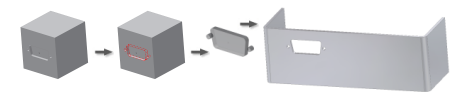
In flat patterns of sheet metal parts, use a simplified sketch to display complex punch features.
First define the size and position parameters for your sheet metal punch iFeature. Then:
- In the Extract iFeature dialog box, Manufacturing area, click Select Sketch.
- In the part browser:
Click the sketch node that defines the iFeature,
or
Click any unconsumed sketch with a single unconsumed centermark defined, that was created to simplify your punch feature in the flat pattern.Note: If attempt to save a sheet metal punch iFeature that contains no centermarks, an error message advises you to edit the sketch to add the centermarks.
Define Optional Depth Parameter
First define the size and position parameters for your Sheet Metal Punch iFeature. Then:
- In the Extract iFeature dialog box, in Depth, Custom, enter a value.
Select Sketch Points for Punch in Sheet Metal
Choose a method to select sketch points to place a punch in a sheet metal part:
- Select a sketch point individually.
- Use auto select to select points in a single sketch.
- To include or exclude all sketch points that touch or are within the area selection box, window select left to right.
- To include or exclude all sketch points that are within the area selection box, window select right to left.
- To remove some points in a window select, or remove some points and add others, window select left to right or right to left.
Extract and Modify Sketch for Sheet Metal Punch iFeature
Extract a sketched feature or a sketch and save it in a catalog. Selected sketches can be either consumed or unconsumed by a feature.
- On the ribbon, click Manage tab
 Author panel Extract iFeature
  .
. - In the Extract iFeature dialog box, select Sheet Metal Punch iFeature as the iFeature type.
- On the model or in the browser, select one or more sketched features to extract. To extract all of the features in a part, select the base feature.
This selection includes any geometrically dependent features. To delete features, use the Extract iFeature dialog box.
- In the Extract iFeature dialog box, left browser column, select one or more feature parameters to use as Size Parameters. Click the right arrow to move them to the Size Parameter area.
- As required, change the Name, Value, and Limit. In Prompt, enter a descriptive instruction to display in the dialog box when the iFeature is placed.
- If necessary, specify a Punch ID, and specify a custom punch depth.
- If necessary, specify an alternative sketch to represent the punched feature when the sheet metal part displays as a flat pattern.
- In the default Punch catalog or another catalog location, save the Sheet Metal Punch iFeature with a unique name.