Sets parameters for a chain design.
Use the Design tab to fully design chain drive layout. You can select appropriate chain as well as add, remove, or reorder sprockets. You have a full control over the drive layout and all geometric properties. Within More Options area you can adjust default behavior of computing number of chain links, and adjust timing.
|
Access: |
Ribbon:
Design tab
 Power Transmission panel
Roller Chains
Power Transmission panel
Roller Chains
|
Chain
|
Use the selection control to browse for appropriate chain within chain library. The chain selection is based on a chain standard (category) and chain type (size of the chain based on pitch). Use the upper part of the panel to select family (standard) of the chain. The selection effects the lower part of the browse window which displays a full list of available chain sizes or solutions for given family. List of the chain families depends on XML data files stored in ...\Design Data\Design Accelerator\Tables\Chains\RollerChains. You can customize list of chains as well as add your own chains according to specific chain supplier. When you finish the chain selection, and the chain corresponds to the input criteria, the |
||
|
Method |
Use the drop-down list to specify the method of a chain selection. The list of chain sizes or solutions in the lower part of the panel has a specific content if different browse method is selected. You can sort the bottom list, as needed. Note: The drop-down list is available only if the Calculation tab is enabled and also Enables/disables the calculation
|
|
|
Browse for a chain by size The content of the bottom list contains all chain sizes of selected chain family. The list contains major dimensional properties of the chain such as chain pitch, or width. Depending on your chain selection the diameters of the sprockets are changed. The number of sprocket teeth is fixed. Click the row to select the chain size. |
||
|
Browse for a solution with fixed number of sprocket teeth The content of the bottom list contains possible solutions of the chain drives that use specific chain size and retain number of teeth of the sprockets. Generator browses for a chain by size and computes strength properties. It preliminary selects what chains might or might not work for such drive. Use this method if diameters of the sprockets are not of a major importance. The static and dynamic safety factors are calculated as well as chain bearing area pressure, overall chain weight, design power and chain power rating. |
||
|
Browse for a solution with closest sprocket diameters The content of the bottom list contains possible solutions of the chain drives that use specific chain size and retain the closest sprocket diameters. Number of sprocket teeth might change accordingly. Generator browses for a chain by size and computes strength properties. It preliminary selects what chains might or might not work for such drive. Use this method if bounding box of chain drive is of a major importance. The static and dynamic safety factors are calculated as well as chain bearing area pressure, overall chain weight, design power and chain power rating for smallest number of teeth in the drive. |
||
|
|
Displays preview and power rating graph of a selected chain or solution. To display the More Options area, click |
|
|
Preview |
Displays a chain preview with appropriate chain dimensions. |
|
|
Power Rating |
Displays a chain power rating graph and a design power for specific application. Refer to the power graph prior the chain selection. Red dot represents the design power. You can easily see if it meets the design criteria (if it is within the recommended range of values). |
|
|
Select Chain Mid Plane |
Select the chain mid plane. You must select a chain midplane to compute initial drive layout and displays dynamic preview of the chain drive. You can select work plane or any planar face within the assembly. You can also use the active coordinate system icon to adjust the X or Y axis direction and the coordinate origin point. |
|
|
Mid Plane Offset |
Controls distance from selected working plane. Insert or measure the value. |
|
|
Number of Chain Strands |
Selects required number of chain strands for the design. Valid strands are determined by selected type of the chain. By changing strand property, you change the chain directly (as simplex, duplex, triples and so on). This value has an impact on the whole chain drive. Sprockets update accordingly and adopt number of chain strands. Use the list to select valid number of strands defined for given chain. |
|
|
Number of Chain Links |
Sets number of required chain links. This edit field is disabled by default. Select Custom in the Chain Options area of the More Options to enable this option. The sliding sprocket position automatically changes its position. Number of chain links is determined from selected chain, position, and size of sprockets. Value is rounded to even or odd number based on a current Chain links option in the More options area. |
|
Sprockets
|
Add, remove, or reorder sprockets as well as set main properties of each sprocket. Each sprocket is represented as 1 line of controls within the list. To reorder the pulleys in the list, drag the lines. |
|
|
There are 3 options that define which action to perform on a sprocket: |
|
|
|
Component Inserts a sprocket as a component. Use this option to create a new part document of the sprocket. The application uses predefined template files for sprocket. You can add additional features into sprocket documents. The file name can be selected within the Properties dialog box. |
|
|
Existing Selects an existing sprocket within the assembly. Use this option if the sprocket that should belong to the chain drive already exists within the assembly. The generator automatically determines position (fixed to the rotation axis) and the number of teeth of the selected sprocket. The generator does not generate sprocket from in-build template. |
|
|
Virtual Does not insert a sprocket into the assembly. This option is similar to the Component option. But no component is created within the assembly. Use this option if it is not clear which sprocket component is used in the assembly. No BOM information is created within the assembly. |
|
Sprocket placement types |
|
|
Each sprocket within the chain drive has a special rule to identify the position of the center: |
|
|
|
Fixed position by coordinates You can drag a sprocket within the main chain plane. Also, you can specify the position by precise values of X and Y coordinates. These coordinates are related to the chain coordinate system. Double-click the sprocket center grip to display the Sprocket's X, Y coordinates dialog box. |
|
|
Fixed position by selected geometry Selection of Work Point, Work Axis, Cylindrical Face, or Sketch Point is required as a geometrical condition of the sprocket center. You cannot specify coordinates by precise numbers. The position is controlled automatically by projecting a center point into the chain main plane. |
|
|
Free sliding position The exact sprocket center is adjusted to accomplish the chain length condition. The sprocket center is specified by a specific point and a specific vector. The closest chain length is selected for actual specific point. The exact sprocket center is then moved along the specific vector until the chain length condition is accomplished. Direction of specific vector is determined automatically by the application and cannot be changed. You cannot specify coordinates by exact values or expressions. |
|
|
Direction driven sliding position Similar to the free sliding position placement. The direction of a specific vector is controlled by selected geometry. Select the Work Axis, Work Plane or Planar Face that needs to be perpendicular to chain plane. You can adjust the specific point only by drag and drop. The generator automatically selects the closest chain length and calculates the exact position of the center to accomplish the chain length condition. The translation plane needs to be perpendicular to the chain main plane. You cannot specify coordinates by exact values or expressions. |
|
|
Rotation driven sliding position Position of the sprocket is determined by Chain Generator with respect to the center of rotation and given arm radius. Use the angle grip to move the sprocket to the appropriate location. Generator automatically advises correct rotation based on a chain length. Center of rotation is defined by selected geometry reference. |
|
Each of the sprockets is editable: |
|
|
|
Sprocket properties Displays the Roller Sprocket Properties dialog box where you can change sprocket parameters (diameter, depth, fillet radii, power ratio and so on). Size of the sprocket can be modified by drag and drop of sprocket size grip within the graphics window. By default, the size of the sprocket can be changed only along with standard (recommended) values. |
|
|
Delete Deletes the sprocket. |
|
|
Browse for sprocket Displays a dialog box to select from filtered sprockets. |

 (More)
|
Displays additional options for chain drive design. To display the More Options area, click |
|||
|
|
Disables the belt coordinate system. Use the on/off switch to hide or show the belt coordinate icon in the graphics screen of your assembly. The active coordinate icon enables you adjust the X or Y axis of the chain coordinate system as well as the system origin point.
|
||
|
Chain Options |
Select the options for spring calculation. |
||
|
Chain Links |
Select the chain links from following types: |
||
|
Even Only |
Generator determines the closest number of links, round it to even number, and moves the sliding sprocket into the necessary position. You cannot enter the chain links manually. |
||
|
Odd or Even |
Generator determines the closest number of links, round it to the closest odd or even number, and moves the sliding sprocket into the necessary position. You cannot enter the chain links manually. |
||
|
Custom |
Enter the required number of chain links. The generator determines the required position of the sliding sprocket. |
||
|
Insert Chain as |
Select an option: |
||
|
Sketch |
Creates chain as a simple sketch. |
||
|
Solid |
Creates the chain as a simple sweep feature. Use this option to visually determine required space for the chain within the assembly. |
||
|
Adjust Timing |
By default the sprocket timing is switched off. This means that sprocket timing is computed automatically based on a driving sprocket position. If you need to adjust sprockets timing, first you need to choose a sprocket with fixed timing constraint. Then, select timing reference geometry (linear entity parallel with main chain plane or planar entity perpendicular to main chain plane). All other sprocket within the chain drive automatically adjusts its rotation to engage with the chain. Use the graphical preview to view the sprocket timing. |
||
Results
|
To display the Results area on the right side of the Design and Calculation tabs, double-click the double line on the right or click the chevron. |
|
Displays summary of dimensional properties of the chain drive as well as calculated dimensional attributes such as pitch diameters of the sprockets or number of sprocket teeth in contact with the chain. Click Calculate to display the values. The units of the results values can be changed. Double-click the specified value you want to change. The following output parameters are displayed in the Results pane. Note: For further description of the calculated parameters, see the Engineer's Handbook
|
|
Summary of Messages
|
Displays the reports about calculation. To open the Summary of Messages area at the bottom of the Calculation and Design tabs, double-click the double line at the bottom of tabs or click the chevron at the bottom of the tabs. |
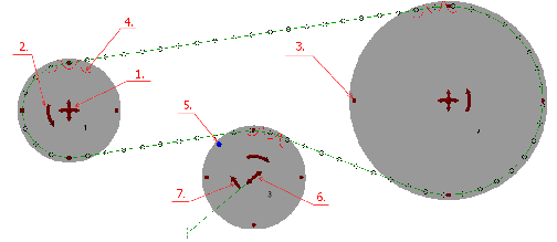
Graphical Preview
|
A graphics preview of the chain drive gives the visual feedback of the designed chain drive and it also helps with the design because you can adjust the chain drive properties using grips. |
|
|
If the chain path with the exact chain pin centers is green, the chain drive trajectory is properly designed and user can initiate calculation. If there is some problem within the geometry design the chain path is red. If there is a specific problem with the given sprocket the sprocket itself turns to the red color. |
|
 |
|
|