The first pulley is considered a driver pulley. The rest of the pulleys are driven pulleys or idlers. Input power can be split among several driven pulleys by using a power ratio factor for each pulley. The forces and torques are calculated accordingly.
Arc of contact correction factor c 1
The arc of contact correction factor corrects the power rating of the V-belt for pulleys where the arc of the contact differs from 180 degrees. The size of the correction factor is determined from the following equation.

Service factor c 2
The service factor takes into account the daily service period and the type of drive units and driven machine. The service factor corrects the power to transmit. Also, consider increasing the service factor for drives with a high starting torque or a high starting frequency, high dynamic loading, or acceleration.
Belt length correction factor c 3
Belt length correction factor takes into account modification of belt power rating for belt which length differs from base belt length. The value is defined by belt manufacturer and it is stated within belt data file. For belt base length the value of length correction factor is 1.0 what does not affect the results.
Number of belts correction factor c 4
The number of belts correction factor takes into account difference of load distribution among multiple belts for transmission where more than one V-belt is used. Difference in load per belt is caused by belt's length difference as well as shaft deformation. The factor corrects the power rating of the V-belt by built-in table of approximate values as follows. The values that are not cited within the table are computed using linear interpolation.
|
z |
1 |
3 |
6 |
999 |
|
c 4 |
1 |
0.95 |
0.9 |
0.85 |
Number of pulleys correction factor c 5
This factor corrects the belt power rating. It takes into account the imposition of additional bending stresses caused by additional pulleys or idlers. Use of an idler (or several idlers) has its effect on belt performance so the belt power rating should be reduced.
In general, idlers are used to provide take-up for drives with fixed center distance, turn corners, break up long spans where belt vibration may be a problem, maintain tension, act as a clutching device and so on. We recommend that you avoid idlers, if possible. If needed at all in the drive, design idler dimensions and locations for a minimum reduction of belt life. Inside idlers should be at least as large as the smallest power transmitting pulley.
Outside idlers should be at least 50% larger than the smallest power transmitting pulley.
The number of pulleys correction factor is by default determined by following built-in table of approximate values. The values that are not cited within the table are computed using linear interpolation.
|
k |
2 |
3 |
4 |
5 |
6 |
7 |
8 |
100 |
|
c 5 |
1 |
0.91 |
0.86 |
0.81 |
0.78 |
0.76 |
0.75 |
0.7 |
Tension factor k 1
The tension factor allows control of initial installation tension of the belt. There are recommended practices provided by belt manufacturers. If a belt is not tensioned according to these recommendations, the belt horse power rating might not be determined properly. The installation tension has a significant impact on the efficiency and belt slip and service live. There is commonly used magnitude of belt tensioning factor from 1.0 up to 1.5 however it is a decisive criterion.
Insufficient belt tension results in inadequate power transmission, reduced efficiency, and premature belt damage due to belt slip.
Excessive belt tension leads to high specific surface pressure, a risk of cross flexing, increased flexing stress and increased strain on the tension members with consequent premature fractures and elongation.
The correct belt tension is just enough tension to keep the belt from slipping under normal load conditions.
Efficiency torque factor η t
The efficiency torque factor describes level of quality of belt transmission. The loss of energy that leads to decreased output torque is considered. Factors like deformation energy of the belt, wind turbulences in grooves, and so on take place. The power loss caused by belt slip is not included here and it is determined by generator separately. Combination of these two factors results in final belt drive efficiency.
Belt slip and total belt drive efficiency η
Belt drive factor is determined at most suspicious pulley as
![]()
Belt slip is defined by built-in slip table.
Driven pulley speed
![]()
Driven pulley output power
P i = P xi F p v η t (1 - s)
![]()
Built-in slip table
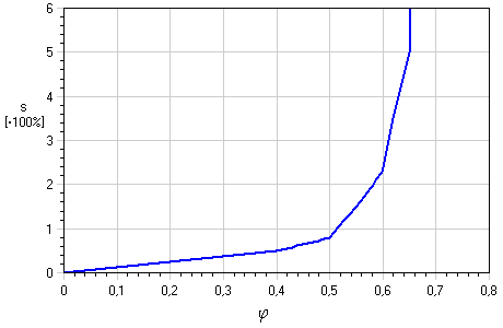
It is assumed that:
- The belt slip occurs on the driver pulley so the speed of all driven pulleys and idlers is influenced by the same slip.
- The belt speed change due to slip is neglected. Usual belt slip magnitude is 1% ~ 2% what results in s = 0,01 ~ 0,02
Transmission ratio
Transmission ratio for V-belt generator is determined for each driven pulley and idler. There are three types of ratios that have specific meaning.
|
i D |
[-] |
Desired transmission ratio (speed ratio) of given pulley. This ratio serves as a design guide for pulley size. User set this ratio to let v-belts generator find closest pulley diameter that accomplish desired transmission ratio. |
|
i T |
[-] |
Ideal transmission ratio (speed ratio) of given pulley. This ratio is calculated directly from pulley diameters as precise value. No belt slip is considered. |
|
i |
[-] |
Transmission ratio (speed ratio) of given pulley. This ratio is calculated with consideration of belt slip. Use this value as closest transmission ratio for your pulley under full load. Power and shaft speed of given pulley is determined using this ratio.. |
Modify friction with belt speed f mod
The modify friction with belt speed factor describes how much the friction factor changes with the belt speed. If the modify friction factor is zero it does not influence the friction factor.
Resultant service factor c PR
The resultant service factor is determined from equation below. The belt power rating for given transmission layout is compared with power to transmit. The resultant service factor gives fast answer of how much the belt drive is over designed.
![]()
|
c PR < c 2 |
Strength check fails |
|
c PR ≥ c 2 |
Strength check succeeds |
|
c PR > c 2 |
Consider to change transmission layout, use different belt or decrease belt width |
Meaning of used variables:
|
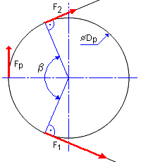
β |
Arc of contact [deg] |
|
F p |
Effective pull (or effective tension) [N] |
|
n 1 |
Speed of the driver pulley [rpm] |
|
n i |
Speed of given driven pulley [rpm] |
|
i |
Transmission ratio (speed ratio) of given pulley [-] |
|
s |
Belt slip [-] |
|
P x |
Power ratio of given pulley [-] |
|
P R |
Belt power rating, power that can be transmitted by one belt [W] |
|
v |
Belt speed [m/s] |
|
η t |
Efficiency torque factor [-] |
|
P |
power to transmit [W] |
|
z |
Number of belts [-] |