You can edit views, specify how they appear, and create drawing views of sketches and sheet metal parts.
What's New: 2022
Edit Drawing Views
You can delete a drawing view or copy and paste a view to another sheet. If you delete a view with dependent projected, section, detail, or auxiliary views, they are automatically deleted.
- In the graphics window or the browser, select the view.
- Right-click and select Edit View from the menu.
- In the Drawing View dialog box, on the Components tab, change the options related to the source model, or any of these additional options:
- Change the model representations.
- Change the view display style.
- Edit the view label.
- Switch the visibility of the view label on or off.
- Click Edit View Label and edit the view label in the Format Text dialog box.
- Select or enter a view scale.
- If you are editing an assembly drawing view, you can do any of the following:
- To change the design view representation, click the arrow, and select a design view representation from the list. Select the Associative checkbox to associate the drawing view with the design view representation in the model.
- If appropriate, select a different positional representation.
- For an iAssembly factory, select the member to represent in the view.
- Select a model state to show only unsuppressed components that participate in the BOM.
Associative Design View Representations
Component transparency is stored in a view representation. A drawing view, that is associated
 with such a design view representation, uses the component transparency setting from the view representation. If your workflow uses associated views, view representations are the preferred method for managing drawing view occurrence display.
Component transparency can be assigned at the view level for non-associated drawing views or by using the component level option "Legacy Transparency." The drawing component setting overrides the model component appearance. This is for non-associative drawing views only.
- On the Model State tab, change the weldment state, reference options, or hidden line calculation options. (Available options depend on the type of file used to create the view.)
- On the Display Options tab, change attributes of display characteristics.
- When you edit a base view, use the direct-editing tools in the graphic window to edit view properties. You can change view orientation, scale, position, or to add and remove projected views.
- Click OK to close the Drawing View dialog box.
Customize Drawing View Orientation
You can customize the orientation of a new or existing view.
Drawing view orientation is usually derived from the orientation of the model. When you create a base view, you can use the view cube to change the model orientation. To create a specific custom orientation, use the Custom View environment.
- Do one of the following:
- To create a view, click
Place Views tab
 Create panel
Base on the ribbon.
Create panel
Base on the ribbon.

Then select a model file in the Drawing View dialog box.
- To change orientation of an existing view, double-click the view.
- To create a view, click
Place Views tab
- Right-click the View Cube, and click Custom View Orientation to enter the Custom View environment.
- Use the Custom View tab to set up the view orientation. For example:
- Click Navigate panel Rotate at Angle (
 ), then use options in the Incremental View Rotate dialog box to set the model orientation.
- Click Navigate panel View Face (
 ) to rotate a model face to the projection plane.
- Click Appearance panel Perspective (
 ) to rotate the model to the perspective position.
- Click Navigate panel Rotate at Angle (
- Click
Custom View tab
Exit panel
Finish Custom View to accept the view orientation and close the Custom View window.
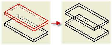
Control Cut inheritance in Child Views
Isometric projected views created for section views inherit the section cut by default. Orthographic projected and auxiliary views support the inheritance of the section, but it is switched off by default.
Isometric projected views created for views with a breakout inherit the breakout cut by default. Orthographic projected and auxiliary views do not support the inheritance of breakout operations.
For orthographic projection, child views inherit breaks by default if the view projection direction is parallel to break lines.
- In the graphic window or the browser, select the child view.
- Right-click and select Edit View.
- On the Display Options tab of the Drawing View dialog box, select the appropriate checkboxes in the Cut Inheritance section. The selected cuts are inherited from the parent view.
Suppress or Unsuppress a Drawing View
The Suppress option specifies whether a drawing view is visible or suppressed. It provides a higher level of visibility control, which supplements the visibility control for components, annotations, model edges, and layer visibility.
Suppressing several drawing views also increases the performance of drawings created for large assemblies.
- When a section view is suppressed, section view sketch (profile) is hidden in the parent view.
- Breakouts hide, if the parent view is suppressed.
- The parent view controls whether an overlay view is visible.
- Do one of the following:
- To suppress a drawing view, right-click a drawing view in the Model browser or in the graphic window, and then in the menu, select the Suppress option.
- To unsuppress a drawing view, right-click a drawing view in the Model browser, and unselect the Suppress option.
Move or Copy Views to Other Sheets
If you place a dependent view on a different sheet than its parent view, a projection line appears next to the parent view. The browser lists the dependent view under its parent view with a shortcut icon.
- To display the dependent view, double-click the shortcut icon.
- To copy views, select views in the browser or display, then right-click and click Copy or use Ctrl+C. To paste you can do either of the following:
- In the browser, select the sheet node and use Ctrl+V or right-click the sheet node and click Paste.
- In the display, position the cursor inside the sheet boundary and use Ctrl+C or right-click inside the sheet boundary and click Paste.
- To move views, in the browser, click the view and drag it to a different sheet node.
- To place a view in a new sheet, click
Place Views tab
Sheets panel
New Sheet and then move or copy the view to the sheet.
Check in the browser to verify that the copy is placed on the new sheet. If it is not visible on the sheet, it may be "behind" another view. Click and drag the views to reveal it.
Create a Drawing View of a Sketch
You can include consumed and unconsumed 2D and 3D sketches in drawing views, even if there is no solid body in the part file. Except for reference parts, a sketch node is created in the drawing browser using the default name of the sketch.
2D sketches are visible only in base views and must be parallel to the view.
- Sketch dimensions are not visible.
- Sketch geometry is not included in hidden line calculations.
- Child views inherit visibility, and sketch inclusion or exclusion from the parent view.
- Sketch nodes in the browser have no Properties option.
- Break-out, detail, and section views trim sketch geometry the same as other model geometry.
In drawing views of parts that contain both solid bodies and sketches, the sketches are not visible by default. If the part file has no solid bodies, sketches are automatically visible in drawing views.
Sketches are not automatically visible for assembly views. Right-click the model in the browser and select Get Model Sketches. Sketches consumed by assembly features cannot be displayed in a drawing view.
If you create a sketch in the drawing, it is not possible to make additional views from this sketch.
- On the ribbon, click
Place Views tab
Create panel
Base and then open a file that contains only sketches or a mixture of sketches and solid bodies.
- In the graphics window, click to place the view.
- (Optional) To add sketches to a view, right-click the sketch node in the browser and select Include. The browser icon changes color to indicate the sketch is visible.
- (Optional) To change the visibility of a sketch in a view, right-click the sketch icon in the browser and select or clear the check mark of the Include option.
- Continue to add views as needed.
Update Drawing Views and Sheets
When significant changes have been made to a drawing, Global Update is the default choice.
If you do not want to trigger Update automatically, you can manually update drawings while you work. The Update command dims when the file is fully up-to-date.
- On the Quick Access toolbar, click the arrow beside Update.
- Select the appropriate option:
- To regenerate only the active sheet, click Update (
 ).
).
- To update all sheets with changes, click Update All Sheets (
 ).
).
- To update this sheet, select the sheet in the browser and click Update.
- To regenerate only the active sheet, click Update (
Adjust the Position of a View on a Sheet
You can drag to re-position a single view or multiple views in a selection window.
When you drag to select views, if you start in in the upper-right corner and drag diagonally from right to left, you include all views that the selection window touches. Dragging diagonally from left to right includes only views that are fully enclosed in the window.
You can also keep the relative position of the view label by constraining it to the view boundary.
- If you are re-positioning multiple views, drag to select them.
- Click and drag the red border for the single view or the selection window.
- (Optional) To keep the relative position of the view label, select the Constrain to View Border option on the View Preferences tab of the Standard panel in Style and Standard Editor.
Redefine XY Planes to XZ Planes
The view orientation (Front, Top, Left, Right, and so on) being used in IDW, Autodesk Inventor View, and 3D DWF are defined by the following mappings.
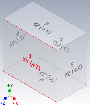

The mapping is fixed and cannot be changed.
The table refers to the parts origin plane when placing a drawing view. For example, XY (+Z) means that you look at the XY Plane from +Z.
Redefining the isometric view in an .ipt (or .iam (in Inventor) file does not affect the mapping.
| Origin folder in IPT (and IAM Inventor) | View orientation in IDW, 3D DWF, and Autodesk InventorView |
|---|---|
|
XY (+Z) |
1 = Front |
|
XY (-Z) |
2 = Back |
|
XZ (+Y) |
3 = Top |
|
XZ (-Y) |
4 = Bottom |
|
YZ (+X) |
5 = Right |
|
YZ (-X) |
6 = Left |
- If the ViewCube is not displayed, click View tab Windows panel User Interface , and select ViewCube.
- Use the ViewCube to reorient the view.
- Right-click the ViewCube and select Set Current View as Home.
Manage Drawing Shaded View Lighting and Reflections
There are three ways to manage the drawing shaded view lighting and reflections: use model IBL Lighting, use model non-IBL lighting, and drawing specific reflection environment.
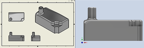
- In the model, activate the desired IBL lighting style. The lighting style image provides the reflection environment. Whenever the lighting style changes, open the drawing and the model view will update to use the same lighting. If the drawing is open, make the drawing the active document and click a view to update all views.
- Application Options > Colors > Reflection Environment has no effect.
- Drawing Document Settings > Drawing tab > Reflection Environment has no effect.
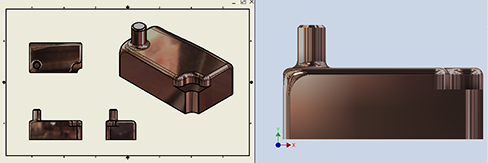
- In the model, activate a non-IBL lighting style. The Application Options reflection environment is used for drawing views. Changing the reflection environment choice will affect drawing views.
- Application Options > Colors > Reflection Environment: specify your selection
- Drawing > Document Settings > Drawing tab > Reflection Environment: Use Application Options

- In the model, activate a non-IBL lighting style.
- Application Options > Colors > Reflection Environment has no effect
- Drawing > Document Settings > Drawing tab > Reflection Environment: Browse... and select the desired reflection environment. To change the reflection environment, browse and select a different one.