You can create weldment models using a combination of welding-specific and assembly commands or convert assembly models into weldments.
Weldment assembly design is an extension of the assembly modeling environment. You can create a weldment two ways. In the weldment environment, use a combination of welding-specific and assembly commands. In the assembly environment, convert the assembly to a weldment. Once converted, you add the weld-specific design intent.
In assembly weldments, you create assemblies, optionally add assembly features to prepare models for welds, add the weld as either a solid or cosmetic feature, and then add more assembly features for final machining operations. Once the weldment model is complete, all parts and features are saved to a single assembly file and called a weldment.
All weldment information, including detailed welding symbols and solid fillet weld bead annotations, can be recovered automatically in drawings. Depending on how you create the weldment, you can also create drawings representing the different states of the weldment.
Creating weldment assemblies
You create weldment assemblies two ways:
- Start a new weldment assembly. Create the assembly, add assembly features, and weld features to the appropriate weld groups to form a weldment assembly. The weldment assembly functions as a single unit.
- Create a regular assembly, and then click Convert to Weldment. The assembly is converted to a weldment, prompting you to set the standard to use, determine the placement of existing assembly features as weld preparations or as post-weld machining features, and select the default weld bead material.
Specifying an assembly as a weldment makes the Weld tab and browser available and applies the default weldment template. If converted from an assembly, no template is applied.
Tasks performed in the weldment environment
As an extension of the assembly environment, you use the weldment environment to perform all tasks included in the assembly environment, plus tasks that are specific to weldments.
Use the weldment environment to:
- Create or open a weldment file.
- Create or insert weldments or subweldments into the weldment assembly.
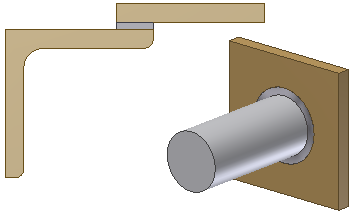
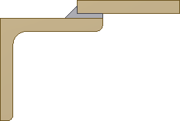
- Optionally create assembly features as weld preparations.
- Create cosmetic weld and solid fillet or groove weld assembly features.
- Create assembly features as post-weld machining features.
- Use the browser to organize and edit assembly features, roll back the weld state, change weld visibility, and suppress features or sketches.
- Document the weldment.
Differences between assemblies and weldment assemblies
When you create or open a weldment file, you are in the weldment environment. The weldment environment contains all the same features and commands of the assembly environment. Additionally, there are commands that are optimized to the weldment manufacturing process. Use these commands to classify and manipulate three groups of assembly features. Optionally, you can create cosmetic or solid fillet and groove welds and associate them with model geometry. The weld feature groups include: preparation features, weld bead features, and post-weld machining features.
When you create or open an assembly file, you are in the assembly environment. In the assembly environment, you can create assembly features. You cannot collect them into weld feature groups, which support the creation of drawings representing the different states of a weldment.
Placing a weldment assembly into other assembly
Weldments can be placed in an assembly, subassembly, or assembly weldment like any other component. Use the Place Component command to select and open the weldment, and then place it in the graphics window.
Once placed, you can edit a weld feature group, change visibility settings, and suppress individual features by activating the subweldment.
Derived weldment assemblies
Weldments can be derived the same as a normal assembly. The weld bead is available to be derived as well, in the Bodies tab. All weld beads are derived together; they cannot be derived selectively.
Weld bead types
Create cosmetic welds (2D and 3D wires) by selecting edges or loops in the model. It is an efficient, lightweight representation. You can request that physical properties include or exclude cosmetic welds by selecting File  iPropertiesPhysicalInclude Cosmetic Welds. You can specify the From-To terminations (parallel) to trim the cosmetic weld bead.
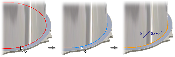
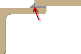
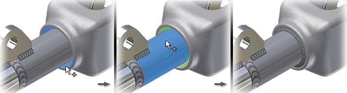
Fillet welds (3D solid) are widely used when no physical gap exists between two or more components. A fillet weld can also bridge a gap between components that do not touch. If a gap exists, the fillet weld spans the gap but does not penetrate the opening. You can create intermittent fillet welds by using pitch, length, and number of bead parameters. You can select Convex, Concave, or Flat Contour options to control the process shape (contour) of the weld. If the weld does not begin or end on an edge, choose Start-Length to specify the offset distance and length value. You can also specify a From-To termination (parallel only) using assembly workplanes or planar geometry to determine the start and end position of the fillet weld bead.
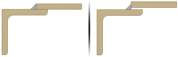
Groove welds (3D solid) are useful when components are separated by a distance or gap. If the Full Face option is not checked on one or either of the face sets, supply either a fill direction or choose the Radial Fill option. Use the Fill Direction selection to specify the direction in which groove weld face sets are projected onto one another to connect by a groove weld bead. Use Radial Fill if a direction pick is not required. Use the Ignore Internal Loops option to control the presence or absence of welds inside of internal loops. Use the Chain Faces option to simplify picking tangent faces.
Often a combination of fillet and groove welds are needed to create a successful weld.
Use the End Fill command to specify explicitly which faces are considered as end fills.