The Roller Chain Generator uses the following theory to advise users if selected chain works under the specified working conditions.
Static factor of safety from chain breaking is determined for constant load as:
![]()
where:
|
S Smin |
Minimum allowed static safety factor [-] |
|
|
F U |
Ultimate tensile strength of the chain [N] |
|
|
F Tmax |
Maximum tension in taught chain span [N] |
Dynamic factor of safety from chain breaking is determined for peak load as:
![]()
where:
|
S Dmin |
Minimum allowed dynamic safety factor [-] |
|
|
F U |
Ultimate tensile strength of the chain [N] |
|
|
F Tmax |
Maximum tension in taught chain span [N] |
|
|
Y |
Shock factor [-] |
Design power and chain power rating
Chain power rating P R is consulted with the design power P D . The chain power rating must be greater than the design power.
P D < P R
where:
|
|
||
|
|
||
|
P |
power to transmit [W] |
|
|
P RN |
Single strand chain power rating for normal operation conditions [W] |
|
|
f 1 |
Service factor [-] |
|
|
f 2 |
Sprocket size factor [-] |
|
|
f 3 |
Chain strands factor [-] |
|
|
f 4 |
Lubrication factor [-] |
|
|
f 5 |
Center distance factor [-] |
|
|
f 6 |
Ratio factor [-] |
|
|
f 7 |
Service life factor [-] |
|
| Φ |
Chain construction factor [-] |
|
The chain power rating is calculated from empirical power rating equations that are unique for the chain. These equations are mentioned in national standards for the steel chains or they come from ACA (American Chain Association) research. These equations may result in different power capacity than what chain producers publish for their chains.
In general, the power rating equations provide valid a power rating for chain drives that work under specific normal operation conditions. If your chain drive works under a working condition that does not equal the normal operation conditions, the generator automatically adjusts the power rating factors accordingly.
More details on power rating factors can be found in the Calculation basics chapter. They are computed with respect to commonly used practice and normal operation conditions.
The power capacity of the chain drives operating within normal conditions is limited by:
- Link plate fatigue P R1
- Roller and bushing impact fatigue P R2
- Galling between the pin and bushing P R3
Example of chain power rating equations
![]()
![]()
P RN = min (P R1 ; P R2 ; P R3 )
where:
|
P R1 |
Chain drive power capacity limited by link plate fatigue [hp] |
|
|
P R2 |
Chain drive power capacity limited by roller and bush impact fatigue [hp] |
|
|
P R3 |
Chain drive power capacity limited by pin-bush galling [hp] |
|
|
z S |
Number of teeth on the small sprocket [-] |
|
|
n S |
Speed of the small sprocket [rpm] |
|
|
p |
Chain pitch [inches] |
P D = P f 1 f 2 f 5 f 6 f 7
P RN = min (P R1 ; P R2 ; P R3 )
![]()
Chain bearing area pressure
During the chain drive service the fluctuating tensile load acts on contact surfaces between pins and bushings what causes specific size of chain bearing area pressure. If this pressure exceeds the permissible pressure in chain bearing area, the chain service life might significantly decrease and the strength check fails. The following equation is checked to pass the strength check successfully:
![]()
The amount of the actual pressure in the chain bearing area is computed from maximum tension in chain span as follows:
![]()
The permissible pressure in the chain bearing area is determined as
p 0 = p B0 . φ
where:
|
p B |
Actual pressure in chain bearing area [Pa] |
|
|
p B0 |
Specific permissible pressure in chain bearing for normal operating conditions [Pa] |
|
|
p 0 |
Permissible pressure in chain bearing area for normal operating conditions [Pa] |
|
|
F Tmax |
Maximum tension in taught chain span [N] |
|
|
A |
Chain bearing area [m 2 ] |
|
| φ |
Chain construction factor [-] |
|
| λ |
Specific friction factor [-] |
Expected service life analysis
The program checks expected service life for
- given chain elongation t h
- link plate fatigue impact t hL
- roller and bush impact fatigue t hR
The strength check succeeds if the required service life is equal or less than any expected service life
![]()
Expected service life for given chain elongation
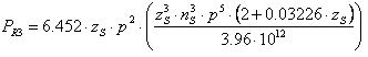
The chain elongates throughout the service life because of the wear. The expected service life when the chain elongation reaches 3% is determined from the following empirical equation

where:
|
t h3% |
Expected service life for chain elongation of 3% [hr] |
|
|
f C |
Wear factor [-] |
|
|
f m |
Specific chain size factor [-] |
|
|
f k |
Chain speed factor [-] |
|
|
X |
Number of chain links [-] |
|
|
v |
Chain speed [m/s] |
|
|
z 1 |
Number of small sprocket teeth [-] |
|
|
z 2 |
Number of small sprocket teeth [-] |
|
|
p |
Chain pitch [m] |
|
|
d 2 |
Chain pin diameter [m] |
|
|
p B |
Pressure in chain bearing area [N/cm 2 ] |
The chain drive with three or more sprockets is substituted with virtual chain drives consisting from just two sprockets. The resultant service life is determined as follows. The chain bearing area pressure is then specific for taught span in each individual virtual chain drive.
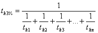
where:
|
t h3% |
Expected service life of chain drive for chain elongation of 3% [hr] |
|
|
t h1 ... t hn |
Expected service life of virtual chain drive for chain elongation of 3% [hr] |
The expected service life for specific elongation what differs from 3% is determined as
![]()
where:
|
t h3% |
Expected service life of chain drive for chain elongation of 3% [hr] |
|
|
t h |
Expected service life of chain drive for given chain elongation [hr] |
|
|
ΔL max |
Maximum chain elongation [-] |
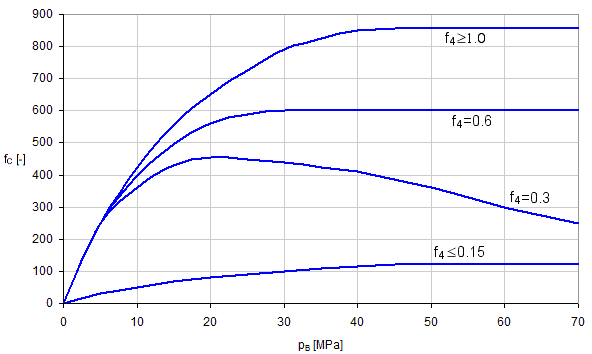
Wear factor f C
Wear factor takes into account quality of lubrication and how much it has an impact on the chain wear progress. The size of the wear factor is determined from the following chart with respect to size of lubrication factor f 4 and bearing area pressure p B .
Specific chain size factor f m
The chain size factor takes into account size of the chain and its impact to the wear progress. The size of the factor is determined from the following table.
|
Pitch [mm] |
4 |
5 |
6 |
6.35 |
8 |
9.525 |
12.7 |
15.875 |
19.05 |
25.4 |
31.75 |
38.1 |
44.45 |
50.8 |
63.5 |
76.2 |
|
f m [-] |
1.64 |
1.57 |
1.54 |
1.53 |
1.49 |
1.48 |
1.44 |
1.39 |
1.34 |
1.27 |
1.23 |
1.19 |
1.15 |
1.11 |
1.03 |
0.96 |
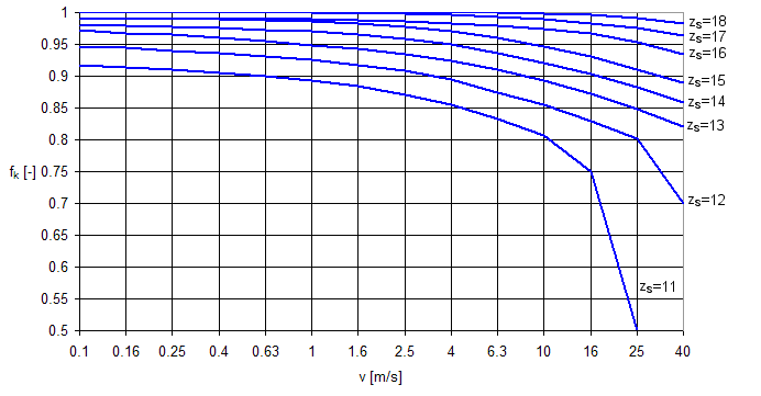
Chain speed factor f k
Chain speed factor takes into account chain speed v [m/s] for a specific number of teeth of the smallest sprocket z s [-]. If the smallest sprocket within the drive has 19 or more teeth the factor always equals to one. If smallest sprocket has less than 19 teeth the speed factor is found in the following chart.
Expected service life due to link plates fatigue
The expected service life without link plate fatigue failure is determined from following empirical equation
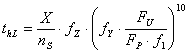
where:
|
t hL |
Expected service life due to link plate fatigue [hr] |
|
|
X |
Number of chain links [-] |
|
|
n S |
Speed of the smallest sprocket [rpm] |
|
|
f Z |
Teeth factor [-] |
|
|
f Y |
Specific chain size factor [-] |
|
|
f 1 |
Service factor [-] |
|
|
F U |
Ultimate tensile strength of the chain [N] |
|
|
F P |
Effective chain pull or tensile load [N] |
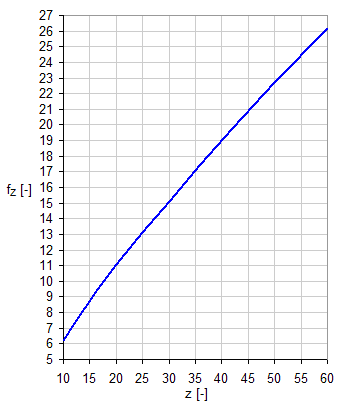
Teeth factor f Z
The teeth factor takes into account modification of service life caused by size of the smallest sprocket in the chain drive. The size of the factor is defined by following chart.
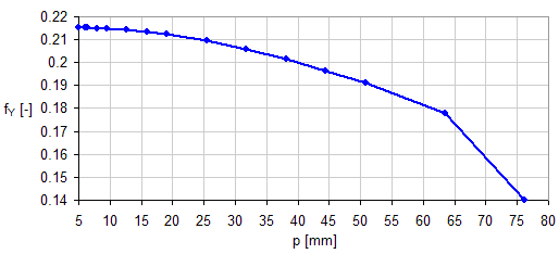
Specific chain size factor f Y
The factor takes into account chain size with respect to peak overloads. The size of the factor is defined by following chart.
Expected service life due to roller and bush impact fatigue
Expected service life without roller and bush impact fatigue failure is defined by following empirical equation:

where:
|
t hR |
Expected service life due to roller and bush impact fatigue [hr] |
|
|
X |
Number of chain links [-] |
|
|
z S |
Number of teeth of the smallest sprocket [-] |
|
|
n S |
Speed of the smallest sprocket [rpm] |
|
|
f 1 |
Service factor [-] |
|
|
f 3 |
Strand factor [-] |
|
|
P |
Power [W] |
|
|
d 1 |
Chain roller diameter [m] |
|
|
d 2 |
Chain pin diameter [m] |
|
|
p |
Chain pitch [m] |