All hole parameters (sizes, start/end plane, and so on) are specified in the Design tab.
Also, you must be connected to the Content Center where the fasteners for bolted connection are stored. If you are not connected to the Content Center, the area on the right side where you select the fasteners is grayed out.
See the About Navigation in the Content Center, or About Configuration of Content Center Libraries to learn how to use the Content Center.
- Access
-
Ribbon:
Design tab
 Fasten panel
Bolted Connection
Fasten panel
Bolted Connection

Type
Select the type of Bolted Connection. Types of holes to select from:
- Through All
- Blind Connection
Placement
Defines the placement of the bolted connection.
First, select start and termination planes. This sequence defines several bolted connection parameters:
- Direction
- Whole plates thickness
- Number of holes
Options to specify the bolted connection position:
- Linear
- You specify the bolted connection placement by selecting the two linear edges.
- Concentric
- You specify the bolted connection placement by selecting a circular edge.
- On Point
- You specify the bolted connection placement by selecting a work point (mainly for non-hole features).
- By Hole
- You specify the bolted connection placement by selecting a hole (it locks bolted connection position, direction, and maximal diameter).
- Start Plane
- Select a bolted connection start plane. Start plane also defines the direction of bolted connection.
- Linear Edge 1
- Select the first linear edge referenced for dimensioning the placement of the hole.
- Linear Edge 2
- Select the second linear edge for hole placement.
- Circular Edge
- Selected circular edge defines the circle, hole is drilled to the center of the circle.
- Point (s)
- Bolted connection is inserted into the selected work point. Recommended when you want to place the bolt to a non-circular hole.
- Existing Hole
- Bolted Connection point is calculated according to the center of the selected hole. At the same time, the maximum possible bolt diameter is restricted by the hole.
- Follow Pattern
- Available only when the By Hole placement option is selected and a hole in the pattern within the graphics window is selected. You can insert into an existing pattern.
- Termination
- Select an end face of the bolted connection. Start plane and Termination restrict the area where the necessary number of holes is calculated.
Thread
Specifies all thread parameters. Selects the thread type and the diameter of a thread. Threads are read from the Threads.xls spreadsheet.
Right side area
Displays the bolted connection components. Select “Click to add a fastener” to add components to the bolted connection.
When selection bolted connection fasteners you can narrow the selection. You can display fasteners according to Standard and Category.
Make sure that you have installed the appropriate libraries to Content Center. For example, you want to insert an ISO washer and you select the ISO Standard from the list but no fasteners are displayed you might have not loaded ISO library.
Also, a selected standard or category may not contain a fastener for particular selection.
- Bolts
- Hex Head Bolts
- Hex Head - Flanged Bolts
- Socket Head Bolts
- Round Head Bolts
- Square Head Bolts
- Countersunk Bolts
- Washers
- Nuts
- Sheet Metal Nuts
Select the row with a fastener. Three options are available to edit the fastener:
-

- For all fasteners: Displays the Table dialog box where you can select from other fastener, if available.
For bolts: Hold the Alt key to open the Modify length/hole dialog box where you can change bolt length
For holes: Displays the Modify length/hole dialog box where you can change hole parameters (type, designation, parameter, and so on).
-

- Deletes the component.
-

- Displays a dialog box where you can select from filtered Content Center items. You can filter the selection by specifying the standard or category. Based on your selection only the fasteners that meet the criteria are displayed. Note: Make sure that you have the library installed in Content Center.
Templates Library
Displays the list of bolted connection templates.
To display the Templates Library, on the Design tab, click ![]() More in the lower right corner.
More in the lower right corner.
Each new bolted connection can be created from a template. When you open the Bolted Connection Generator, click Set to apply the template to the currently designed bolted connection.
Now, templates library remembers recently used template.
- Set
- Applies selected template to a current content of the bolted connection.
- Add
- Adds a newly designed bolted connection to the template library. Note: Add command is available when the complete geometry of bolted connection is specified, including start plane, reference, and an end plane.
- Delete
- Deletes the selected bolted connection template.
Tips:
- When you double-click a template, you can change the template description, if needed.
- Using drag&drop method you can reorder templates within the library.
Summary of Messages
Displays the reports about calculation. To open the Summary of Messages area at the bottom of the Calculation and Design tabs, double-click the double line at the bottom of tabs or click the chevron at the bottom of the tabs. The Message area incorporates a summary for all calculations (state and fatigue).
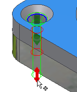
Graphical Preview
A graphic preview represents the selected geometry and bolted connection components. The preview is a schematic representation of a fastener. The preview includes the visibility of counterbore/countersunk hole geometry and differentiates between socket head bolts and hex head bolts.
Preview displays in the graphics window when you select first fastener in the Design tab.