A flange can be along an edge or loop, or identical to an existing face.
What's New: 2021
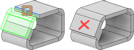
If the faces merge, try using an offset plane to define the flange.
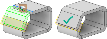
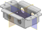
Create Flange along Edge or Edge Loop
You can add a sheet metal face and bend connected to an existing sheet metal face with a specified angle. When you create the flange, the flange previews along the edge you select using default parameters.
- On the ribbon, click
Sheet Metal tab
 Create panel
Flange
Create panel
Flange
 .
.
-
Do one of the following:
- To create flanges along edges, click Edge Select Mode, and then select one or more edges.
- To create multiple flanges around an edge loop, click Loop Select Mode, and then select a loop.
- In the Height Extents drop-down list, do one of the following:
- Select Distance and enter a value in the drop-down list below it.
- Select To and specify a geometry that defines the flange height.
- (Optional) To change the side of the sheet metal face that the flange is on, click Flip Direction.
- Specify the following:
- Set the Flange Angle option to By Value to define the angle of the flange relative to the face containing the selected edges.
- Enter the angle value. The field accepts numeric entries, formulas, parameters, or measured values.
- Specify the Bend Radius or accept the default BendRadius parameter.
- If not the intersection of the two outer faces, specify the datum from which to measure the height.
- If you do not want the outside face of the bend to align to the selected edge, specify the bend position relative to the selected edge.
- (Optional) To add more flanges, click Apply.
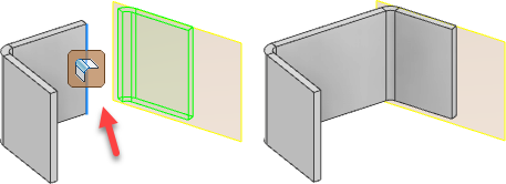
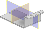
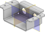
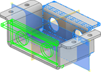
Create Flange aligned with a Face or Plane
You can add a sheet metal face and bend connected to an existing sheet metal face with an angle that matches your selection. When you create the flange, the flange previews along the edge you select using default parameters.
The original face is extended or trimmed to attach the flange to the reference plane.
- On the ribbon, click
Sheet Metal tab
Create panel
Flange
.
- Click Edge Select Mode, and then select an edge.
- In the Height Extents drop-down list, do one of the following:
- Select Distance and enter a value in the drop-down list below it.
- Select To and specify a geometry that defines the flange height.
- (Optional) To change the side of the sheet metal face that the flange is on, click Flip Direction.
- Specify the following:
- Set the Flange Angle option to By Reference to match the angle of the selected planar face, planar surface, origin plane, or work plane.
- Select the reference plane.
- Set the Bend Position to Inside of Reference Plane, or Outside of Reference plane.
- Specify the Bend Radius or accept the default BendRadius parameter.
- If not the intersection of the two outer faces, specify the datum from which to measure the height.
- (Optional) To add more flanges, click Apply.
Specify Flange Width
The More panel of the Flange dialog box provides additional ways to specify flange width.
- On the lower right of the Flange dialog box, click More.
- Select one of the following on the Extents Type drop-down list:
- To create a flange that extends along the entire edge, click Edge.
- To specify a specific width, click Width and enter the value. Then specify Centered or Offset to adjust the flange.
- To use an offset for the width, click Offset and specify values in the Offset1 and Offset2 drop-down lists.
- To use values of existing geometry, click From/To, and then select the beginning model geometry for Offset1, and the end geometry for Offset2.
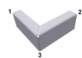
Create 3-Bend Corner on Flange Using Auto-Miter
The corner relief type and radius size specified in the corner tab of the feature apply when you create your flat pattern and do not display in the folded model.
- On the ribbon, click
Sheet Metal tab
Create panel
Flange
.
- Select two coplanar edges that share a virtual corner. In the Flange dialog box, Corner tab, verify that Apply Auto-Mitering is selected.
- Specify the flange parameters, and click OK.
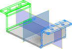
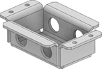
Create Symmetrical Flanges
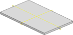
- Start by creating a Face symmetrical about the Origin planes or work planes.
- Create the flanges and other features to mirror.
- Start the Mirror command. Select all the features that you want to mirror, select the mirror plane, and then click OK to finish.
- Create the next set of flanges and other features to mirror.
- Start the Mirror command. Select all the features that you want to mirror, select the mirror plane, and then click OK to finish.
For more information, see: