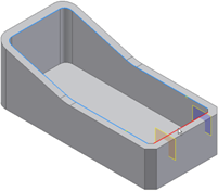
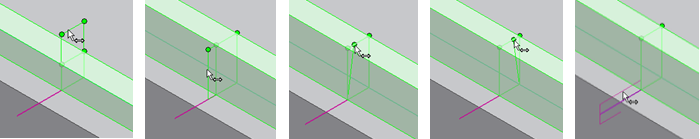
Limit the lip extension on one of the paths to two trimming planes.
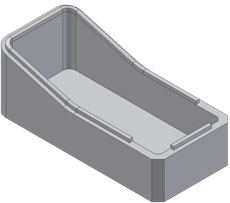
Before starting, create or import a thin-walled part with a path that consists of a set of smoothly connected boundary edges (tangent continuous). Define two work planes and two work points along the path.
- Click 3D Model tab
 Plastic Part panel Lip
  .
. - In the Lip dialog box, choose the type of lip you want to create, Lip or Groove.
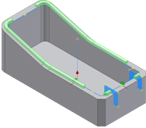
- Using the Path Edges selector, select one or more paths.
Each path must be tangent continuous. All the paths of the same lip or groove must stay on a tangent continuous face.
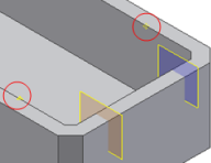
Note: Do not select the chamfer edges; leave the path open. - Using the Guide Face selector, select the face of the thin-walled part to be the guide. The guide face has the path edges on its neighborhood. If selected, Guide Face keeps the cross section of the Lip/Groove at a constant angle along the path.
- Use the Pull Direction selector to choose the Pull direction.
The Pull Direction is alternative to the Guide Face. When selected, ensures that the Lip/Groove cross section stays parallel to it along the entire path.
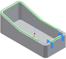
- Use the manipulators in the graphics window to adjust the cross section and the clearance volume. You can drag the cross section to a more convenient location along the path.
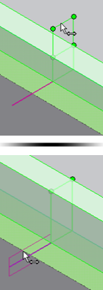
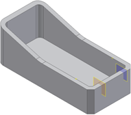
- Use the Path Extents selector to select the two planes and the two points. At first, the Lip algorithm makes a tentative choice of sectors. Use the green and yellow dots to choose which sections to keep or remove.
- In the Lip or Groove tab of the Lip dialog box, specify the geometric parameters of the lip or groove. You can use precise input in the text boxes or use the manipulators that allow the interactive dimensioning of all the parameters. The geometric parameters include lip draft angles, lip height, lip thickness, shoulder width, and clearance height.
- Click OK.