Create an iPart configuration
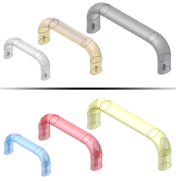
A good candidate for an iPart is a basic part you use often in different sizes, materials, or mounting configurations. When you transform a part to an iPart, you define the parameters and properties that must change for each part.
You can also create a table-driven iPart and use it to create a table-driven iFeature if the entire part is going to be used as an iFeature. Use the Extract iFeature command to save the iPart as an iFeature. Once the table-driven iFeature is saved to the catalog location, use the iFeature Author to make changes to the table.
In the iPart Author table, you define individual members of the iPart by specifying its values. If you prefer, you can add or edit members in an embedded Microsoft Excel spreadsheet. For standard iParts, each table row is a member of the iPart.
In previous versions, legacy iParts concatenated Key values to create a file name. Now, a Member column in the iPart table generates a default file name based on the iPart name. Each member name is incremented. Optionally, click Options in the iPart Author dialog box to set up a different naming scheme, or enter a new name in the member cell.
In previous versions, legacy iParts concatenated Key values to create a file name. Now, a Member column in the iPart table generates a default file name based on the iPart name. Each member name is incremented. Optionally, click Options in the iPart Author dialog box to set up a different naming scheme, or enter a new name in the member cell.
You can create a standard iPart or a custom iPart.
Set up part parameters
 |
It is a good idea to create the part relatively close to its actual size and then use dimensions to make the sketch geometry precise. You can edit dimensions if you need to when building the iPart table. If you know that you want the part to be a table-driven part, create parameters with meaningful names as you add dimensions. For example, in the dimension edit box, type in Length=75mm. The sketch length will change to 75mm, and a parameter will be created and added to the table with the name of Length. Parameters appear in the order you add them in the iPart table. Give some thought to the order you add them so that related parameter columns are grouped . |
|
|
|
 In this example, dimensions are shown as d0 and d1. You can create the parameters Length and Width as you add these dimensions or you can open the Parameter table and rename them to Length and Width.
Create a standard iPart
- Click
Manage tab
 Author panel
Create iPart to open the iPart Author. All parameters renamed in the Parameters dialog box are already added as columns in the iPart table.
Author panel
Create iPart to open the iPart Author. All parameters renamed in the Parameters dialog box are already added as columns in the iPart table.
If you did not rename the parameters, add them to the table individually.
- In the left pane, the browser shows all part data. Click a parameter and then click the Include arrow to add the parameter to the table.
To remove a parameter, click the parameter in the right pane and then click the Remove arrow.
Tip: Each selected value is a column in the iPart table, so include only items that need different values in iPart members. - Click tabs and add needed attributes. For example:
- On the Properties tab, expand the Project folder and add Part Number. In the iPart table, give each member a unique part number. When you place a version of the iPart, your bill of materials and parts lists are up to date.
- On the Suppression tab, add features whose suppression status you want to control.
Tip: When creating a part, you can suppress features and add new ones, so that you can define multiple configurations of a part in a single file. In the iPart table, you can change suppression status of features for each member.
- On the iFeatures tab, add inserted iFeatures you want to include in the table. You can specify the iFeature row value and suppression status for each row in the iPart table.
- On the iMates tab, iMates are automatically included if the feature status is Compute, but are not included if Suppressed.
- On the Work Features tab, include one or more work features, if desired. Work features may be useful when constraining parts in an assembly. For electrical parts, work features are included by default.
- On the Work Features tab, include one or more work features, if desired.
- On the Work Features tab, include one or more work features, if desired. For electrical parts, work features are included by default.
- On the Threads tab, include or exclude thread parameters, if present. Family is a crucial distinction among threads, so include it as a minimum.
- On the Sheet Metal tab, include: Sheet Metal style, Sheet Metal Unfold style and/or Flat Pattern Orientation as needed for your configuration.
- On the Other tab, create values such as Color, Material, or File Name.
The Member Name column automatically generates unique names to distinguish each iPart member.
If you alter the member name from the default, it alters the file name.
- Review the columns in the iPart table to determine which columns to designate as Keys, such as material or size, by identifying primary characteristics of the iPart.
Note: If the iPart is going to be exported as an iFeature, you can designate the Key1 value to identify a specific characteristic of the iFeature in the browser of the part file it is used in.
In the right pane, right-click an attribute and select Key. Click the arrow and select the number to specify the order. For example, if you always select a part by its length, and then its width, designate length as Key1 and width as Key2.
Tip: Key values are listed in order in the browser and the Keys tab of the Place iPart dialog box. Specify only needed keys to avoid browser clutter. Key columns are indicated with a key icon. - Right-click in the table and select Insert Row. Modify the values as needed to create an iPart member.
You can continue to add rows and columns as needed. Consider editing the table in a spreadsheet so you can take advantage of functions such as copy and paste, formulas, and sorting.
- Right-click a table row and select Set as Default Row. The default row is indicated by a green background. The Default Row is automatically inserted into an assembly when placed, unless a different iPart member is selected.
- Right-click a table row and select Set as Default Row. The default row is indicated by a green background.
- Click OK to create the iPart. You can edit the iPart later to add or remove rows or adjust your preferences.
- Save the file.
Create a custom iPart
- Create a standard iPart, using the instructions in the previous section.
- On one or more tabs in the iPart Author, determine the custom values to enter when the iPart is placed.
- If the value is not already in the iPart table, select it in the left pane, and then click the Include arrow to add it.
- In the iPart table, specify cells or columns in which to enter a custom value:
- Right-click in a column and select Custom Parameter Column.
- Right-click in any cell and select Custom Parameter Cell. Use this technique to create only one row that allows custom entry.
A custom column or cell is indicated by a blue background.
- Save the file.
Sheet metal parts can include features added to the flat pattern. When such a part becomes a custom iPart these flat pattern features cannot be:
- driven through the use of parameters
- suppressed
Custom iPart Example: Calculate custom parameters in Microsoft Excel
Setting a column to Custom means that you are able to set the value independently of the iPart table for that member.
You can use custom parameters to calculate values in the iPart table. Cells and columns calculated in Microsoft Excel have a red background when viewed in the iPart table.
 |
 |
|
In the iPart, a column was added using the Description property. |
Using a Microsoft Excel formula in the Description column, each iPart version was automatically calculated. |
Consider the iPart example shown previously:
- In the part file, use the Parameters command to add User Parameters for Width, Height, and Length.
- In the iPart Author, specify five columns:
- On the Parameters tab, select Width, Height, and Length.
- On the Properties tab, select Description and Part Number.
- Right-click the Length column and set it as Key1. When the iPart is placed in an assembly, only its length (Key1) is shown in the browser.
- Right-click the Length column and set it as Key1.
- Click OK to close the iPart Author dialog box and save the file.
- Right-click the table in the part browser and select Edit via Spreadsheet.
- In the spreadsheet, Width, Height, and Length are in columns A, B, and C. In cell D2 (the first data row) of the Description column, enter the formula:

This formula retrieves the values in columns A, B, and C and calculates results in the Description column. Using your values and units, the results look like the following formula:
2 mm x 10 mm x 50 mm
Each member of the iPart is calculated separately.
- Save the spreadsheet.
Generate new member files
After you have created member rows in the iPart, you can generate the files.
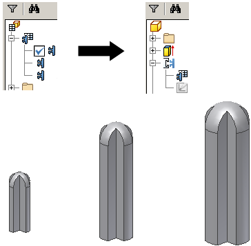
- In the browser, click to expand the iPart. The member names are nested below.
- Right-click a member name and select Generate Files to create the file on your computer. It is located in the same folder as the parent file.
- Continue to select members and generate files.