Insert bolted connections
All hole parameters (sizes, start/end plane) are specified in the Design tab.
Also, you must be connected to the Content Center where the fasteners for bolted connection are stored. If you are not connected to the Content Center, the area on the right where you select the fasteners is dimmed.
 By default, the sub-assembly structure is disabled, and the bolted connection parts are created at the root level of the assembly. You cannot enable Automatic solve using this structure. You must use Manual solve to update the bolted connection.
 Enable the sub-assembly structure to create a sub-assembly containing the bolted connection parts at the root level of the assembly. Prior to Inventor 2021, this was the only option for creating bolted connections. Use this option if you want to enable Automatic solve.

See the Content Center Help, or About Configuration of Content Center Librariesto learn how to use the Content Center.
Access
On the ribbon, select
Design tab
 Fasten panel
Bolted Connection
Fasten panel
Bolted Connection
![]() .
.
On the Design tab:
- In the Type area, select the type of bolted connection (If your assembly contains only one component, select Through All connection type).
- Select the type of placement from the Placement drop-down menu.
- Linear specifies the placement by selecting two linear edges.
- Concentric specifies the placement by selecting the circular edge.
- On point specifies the placement by selecting a point.
- Hole specifies the placement by selecting a hole.
- Specify the position of your bolted connection. According to your placement selection, you are prompted to specify a start plane, edges, point, hole, and termination plane. The options displayed depend on your selected placement type.
- Specify the bolted connection placement to select fasteners to the bolted connection. The Bolted Connection Generator filters the fasteners selection based on placement specifications made on the left side of the Design tab. When the placement specifications are not made, the fastener options on the right side of the Design tab do not enable.
- Insert a bolted connection to an assembly that contains two or more components, and select Blind Connection type. In the Placement area, you are prompted to select Blind Start plane (not termination plane) to specify where the blind hole starts.
- In the Thread area, specify the thread type from the Thread drop-down menu, and select the Diameter dimension.
- Begin populating the bolted connection.
- Select Click to add a fastener to connect to the Content Center where you select the component.
- Begin populating the bolted connection. Follow the instructions on the right side of the Design tab. Select Click to add a fastener to connect to the Content Center where you select the component. Continue populating the connection by selecting appropriate content.
- (Optional) In the right lower corner of the Design tab, select More
 . Save your bolted connection to the templates library.
- Select Add and specify the template description.
- Select Apply to leave the Bolted Connection Generator open.
- Select OK to insert bolted connection to the assembly.
Insert bolted connections using linear placement option
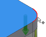
Select linear type of placement to specify the bolted connection position by selecting two linear edges.
To insert a bolted connection using the Bolted Connection Generator, your assembly must contain at least one component.
- On the ribbon, select
Design tab
Fasten panel
Bolted Connection
 .
.
- In the Type area of the Design tab, select the type of hole.
- On the Design tab, Placement area, select Linear
 from the drop-down list.
- In the graphics window:
- Select the start plane. After the selection, other buttons for placement are enabled (Linear edge 1, Linear edge 2, Termination).
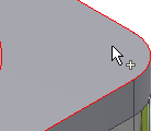
- Select first linear edge.

- Select second linear edge.

- Select the termination plane.
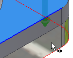
- Select the start plane. After the selection, other buttons for placement are enabled (Linear edge 1, Linear edge 2, Termination).
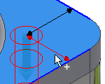
 In the graphics window, select the 3D grip to edit the distance of hole center from selected linear edges. Select the button to confirm the distance.
- In the Thread area, select the type and diameter of thread.
- Select Click to add a fastener text in the right area of the Design tab and populate the bolted connection.
- (Optional) On the Design tab, right lower corner, select More
to save your bolted connection to the templates library. Select Add and specify the template description.
- Select OK to insert bolted connection to the assembly.
Insert bolted connections using concentric placement option
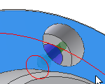
Select the concentric type of placement to specify bolted connection placement by selecting the circular edge or edges. Hole for bolted connection placement is inserted into the center of circle defined by circular edge.
- On the ribbon, select
Design tab
Fasten panel
Bolted Connection
.
Note: To insert bolted connection using Bolted Connection Generator, your assembly must contain at least one component.
- In the Type area of the Design tab, select the type of hole.
- On the Design tab, Placement area drop-down list, select Concentric
 .
.
- In the graphics window:
- Select the start plane. After the selection other options for placement are enabled (Circular reference, Termination).
- Select circular edge.
- Select the termination plane.

- Select the start plane. After the selection other options for placement are enabled (Circular reference, Termination).
- In the Thread area, select the type and diameter of thread.
- Select the Click to add a fastener text in the right area of the Design tab and populate the bolted connection.
For more options:
- (Optional) On the Design tab, lower corner, select More
. In the More Options area, you can save your bolted connection to the templates library. Select Add and specify the template description.
- Select OK to insert bolted connection to the assembly.
Insert bolted connections into patterned holes
When creating patterned holes using the Autodesk Inventor Hole command as multicenter point holes, insert the bolted connection into such patterned holes using Bolted Connection Generator. This generator recognizes your design contains a pattern and enables the option to insert a bolted connection into patterned holes.
- Place the hole feature in a part environment.
- Create the hole pattern in a part environment (not in an assembly).
- Return to the assembly from editing the part.
- Open the Bolted Connection Generator.
- In the Type area of the Design tab, select the type of hole.
![]()
- Select By hole from the drop-down list in the Placement area of the Design tab.
- In the graphics window:
- Select the start plane.

- Select the Existing hole. When your design contains a patterned hole, the Follow Pattern box is enabled.

- Select the termination plane.
- Select the start plane.
- In the Placement area of the Design Tab, check Follow Pattern box. A bolted connection is inserted in every patterned hole.
- In the Thread area, select the type and diameter of thread.
- Select the Click to add a fastener text in the right area of the Design tab and populate the bolted connection.
- Click OK.
 When you insert bolted connection into pattern, you delete all bolted connections inserted into such pattern.
![]()
Insert bolted connections to sketched points
If your assembly contains point created in sketch environment you can insert bolted connection to such points.
- Create points in sketch environment.
- Return to the assembly from editing the part.
- Open the Bolted Connection Generator.
- In the Type area of the Design tab, select the type of hole.
![]()
- On the Design tab, Placement area drop-down list, select On point
 .
.
- In the graphics window:
- Select the start plane.

- Select the point. When your design contains a sketched point, the Follow Pattern box is enabled. By default, bolted connections are inserted into every sketched point. To add or remove points, hold the Ctrl key + select the point.
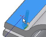
- Select the termination plane.

- Select the start plane.
- In the Thread area, select the type and diameter of thread.
- Select the Click to add a fastener text in the right area of the Design tab and populate the bolted connection.
- Click OK.
During edit, add or remove bolted connections from patterned points. In the assembly, right-click and select Edit Using Design Accelerator. On the Design tab, select Points. In the graphics window, select the point from which to remove the bolted connection. Hold down the Ctrl key to remove more bolted connections from point at the same time
Bolted connections inserted using Bolted Connection generators are mated to selected points. When, within the sketch environment, you move the points, all inserted bolted connections are moved also.
Insert bolted connection onto extruded or revolved cuts
It is also possible to insert bolted connection into holes created using Extrude and Revolve commands in part environment.
- Create holes using Revolve or Extrude commands in part environment.
- Return to the assembly from editing the part.
- Open the Bolted Connection Generator.
- In the Type area of the Design tab, select the type of hole.
![]()
- Select Concentric from the drop-down list in the Placement area of the Design tab.
- In the graphics window:
- Select the start plane.
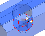
- Select the circular edge. When your design contains a patterned hole, the Follow Pattern box is enabled. By default, bolted connections are inserted into every patterned hole.
- Select the termination plane.
- Select the start plane.
- In the Thread area, select the type and diameter of thread.
- Select the Click to add a fastener text in the right area of the Design tab and populate the bolted connection.
- Click OK.
![]()
Insert bolted connections using custom fasteners
You can insert bolted connections using your own fasteners added to Content Center. You must author and publish your components first, and then you can insert them into the assembly using Bolted Connection Generator.
- Create or open en existing company part in the Part environment.
- Select the
Manage tab
Author panel
Component to author the part or iPart. To learn how to author iPart click here.
- Ensure that you have a Read/Write library created and added in your current project.
- Select the
Manage tab
Content Center panel
Publish Part to publish an iPart or part. To learn how to publish iPart click here.
- Open Bolted Connection Generator. Authored and published parts are available for selection.
- Specify bolted connection placement.
- Populate bolted connection
- Click OK.
![]()
The Bolted Connection displays parts according to filter the thread type and Bolt Diameter. For example, ISO Metric profile and 6 mm. If your part does not correspond with this filter (does not have a member with 6 mm diameter), the part is not displayed in the bolted connection.
Add bolted connections to Templates Library
You can save the bolted connections to Templates Library.
To display the Templates Library, on the Design tab, select
![]() More in the lower right corner.
More in the lower right corner.
In the Templates Description dialog box, set the template name, and click OK.
Template Description dialog box
- Access
- Ribbon:
Design tab
Fasten panel
Bolted Connection
and on the Design tab, in More Options, select Add.
Any new bolted connection can be used as a template. Save it to the Templates Library on the hard drive. The next time you create a new bolted connection, the new template is available.
Use Sheet Metal fasteners in bolted connections
Using bolted connection generator, you can insert sheet metal nuts only.
- Populate the bolted connection and select a bolt.
- To select a Sheet Metal nut, select the Click to add a fastener option.
- Select all options in the Standard drop-down menu and Sheet Metal Nuts in the Category drop-down menu.
- Click to select and insert a Sheet Metal nut into the Design tab of the Bolted Connection Generator.
- Finish populating the bolted connection and click OK.
- To change the Sheet Metal nut in the designed bolted connection, select the nut and click
 .
.
- Select
 to open the Table dialog box. The Table dialog box offers a selection of more nuts.
Additional insertion of connection components
- Open the Autodesk Inventor assembly with the already inserted Design Accelerator bolted connection.
- Select the bolted connection, right-click to display the context menu, and select the Edit Using Design Accelerator command.
- In the right side of the Design tab, add or delete components.
- Click OK to insert updated bolted connection.
![]()
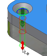
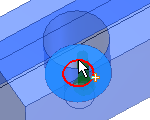
Graphics preview
A graphic preview represents the selected geometry and bolted connection components. The preview is a schematic representation of a fastener. The preview includes the visibility of counterbore/countersunk hole geometry and differentiates between socket head bolts and hex head bolts.
- Select the fastener in the Design tab.
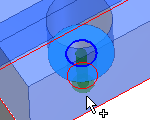
- Use the 3D grips within the preview to edit bolt length.
- Drag the 3D grip to an appropriate length. Only lengths available for selected bolts are available.
- A tooltip is displayed showing the fastener dimension. Double-click the 3D grip to display the Modify dialog box where you can select the dimension from list of available dimension for particular fastener.
Preview displays in the graphics window when you select first fastener in the Design tab.