When surface data is imported and translated with Autodesk Inventor, faces can be trimmed in unexpected ways. To repair surfaces:
- Use Extract Loop to untrim surface loops, leaving the wires intact. When extracted, loops are changed to wires. You can optionally copy or delete the wires from the original surface edges if you are not going to use them in repairing the surface.
- Use Boundary Trim to generate and rebuild a new surface using the surrounding surface edges or wires in the file.
The following two tasks show a typical workflow for repairing a loop using the Extract Loop and Boundary Trim commands.
Extract a Loop

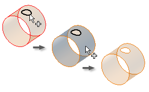
The Extract Loop command works only on a single face. Only wires or edges of faces are valid selections.
- Data is translated into the repair environment, and the find errors (repair environment) or quality check (construction environment) command reports a bad loop on the highlighted surface.
- On the ribbon, do one of the following:
- Click Repair tab
 Modify panel Extract Loop.
 - Click Construction tab Surface panel Extract Loop.
- Click Repair tab
- Select the surface or an edge of the surface that you want to untrim. The arrow color in the Loop command changes from red to white. Note: Right-click to select an option to undo the last selection.
- To specify that the existing edges of the surface are to become new wires, make sure Delete Wires is cleared. Otherwise, select Delete Wires to use adjacent face edges for trimming.
- Click Apply. The untrimmed surface is equivalent to the bounding size of the surface.
- Select another surface edge to extract, or click Done.
Note: Change the visibility of the surface to make selecting edges easier.
Use Boundary Trim
- On the ribbon, do one of the following:
- Click Repair tab Modify panel Boundary Trim.
- Click Construction tab Surface panel Boundary Trim.
- Click Repair tab
- Click Cutting Edges if it is not already selected, and select the first edge of the boundary.
The red arrow in the Cutting Edges command changes to white when the first edge is selected. As you pause the cursor over an edge, its color changes to red. Only valid wires that intersect can be selected. When the edge is selected, the color changes to cyan (blue-green).
Note: Only wires or edges of faces are valid selections. Right-click to select an option to undo the last selection. - Continue selecting edges until they form a closed boundary. When all edges are selected, the color of the closed loop changes to black, and Loop or Face is enabled (its arrow turns red). Note: Once the closed loop is formed, you cannot cancel the selection of any of the previously selected edges.
- In the Boundary Trim dialog, click Face or Loop if it is not already selected.
- A preview of the surface is displayed. You can choose which side of the surface to keep.
- Click Apply to trim the surface. Click Done after you trim all surfaces.