You can create a flat pattern from a sheet metal model and display the correct iProperties for a folded model and a flat pattern.

Before you create the flat pattern, you can define the A-Side or select a face to unfold from. The A-Side specifies the up direction of the part. A selected face unfolds the part using the selected face as the base face.
To create a flat pattern from a part created using only conical or cylindrical features and then converted to sheet metal, preselect a curved face.
You can reorient a flat pattern using any straight feature edge, virtual line between two vertices, or line of tangency.
Define A-Side
- With a sheet metal part open, on the ribbon, click
Sheet Metal tab
 Flat Pattern panel
Define A-Side.
Flat Pattern panel
Define A-Side.
- Click the face that defines the up or punch direction. A browser entry is created.
- Optionally, create a flat pattern. The A-Side is defined and a browser entry is created when you create the flat pattern.
- If no flat pattern exists, you can delete the A-Side Definition entry in the browser and then redefine the A-Side. If a flat pattern exists, you must delete the flat pattern before you can delete the A-Side browser entry.
Note: Deleting a flat pattern also deletes the flat pattern views in associated drawings.
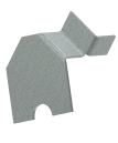
Create a Flat Pattern from a Sheet Metal Model
Before you create the flat pattern, you can define the A-Side or select a face to unfold from. The A-Side specifies the up direction of the part. A selected face unfolds the part using the selected face as the base face.
- With a single body sheet metal part open, on the ribbon click
Sheet Metal tab
Flat Pattern panel
, click
Create Flat Pattern.
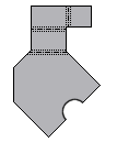
The flat pattern is created, and displays. A Flat Pattern node is created in the browser.
- In the browser, double-click the Folded Model node to return to the folded model or,
click Flat Pattern tab
Folded Part panel
Go to Folded Part.
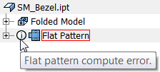
A flat pattern that has compute errors is marked by an information icon in the browser and participates in the Design Doctor.
Display Correct iProperties for a Folded Model and a Flat Pattern
The iProperties reflect the correct physical properties for the folded model or displayed flat pattern (including any material added or removed using feature edits in the flat. and excluded punch features displayed as center marks or as center marks and sketch).
If you now save the part, and retrieve the mass for a drawing view annotation, the value reflects the folded model mass.
- On the ribbon, click
Manage tab
Update panel
Rebuild All.
- In the browser, double-click the node for the flat pattern or folded model.
- Right-click the top-most node, and click iProperties...
- On the Physical tab, click Update, and then click Close.
- In the browser, double-click the node for the folded model or flat pattern.
- Right-click the top-most node, and then click iProperties...
- On the Physical tab, click Update, and then click Close.
Export Flat Pattern
You can export a flat pattern of a sheet metal model to SAT, DWG, or DXF file types. You start with an existing flat pattern.
- Most machine tools require data in R12 format.
- Not all machine tools require all of the available layers.
- Pay attention to the front and back attribution. Certain punches strike from the front or back and do not apply to the file you are exporting.
- Inner profiles are shapes created using a cut feature and can represent laser or water jet cut paths. Feature profiles are shapes created using punch tools. Depending on the machine tool you target, consider using these layers separately.
- You can reuse the configuration of a file type, layer, and geometry options, click Save Configuration, and enter a meaningful name.
- When you set Geometry options, many machine tools expect the external profile of a flat pattern to be represented as a polyline. Some machine tools expect all XY geometry to have a positive sign (for example, exist within first quadrant). Check the requirements of your target machine.
- Some shop tools are unable to use exported DWG or DXF flat pattern file when a bend centerline crosses a hole in the bend. Select the Geometry tab in the Flat Pattern DXF or DWG Export Options dialog box. Check the Trim Centerlines at Contour option in the Geometry tab to trim bend centerlines to the edge of the cut.
- In the browser, right-click the icon for the flat pattern click Save Copy As, browse to the desired folder, and then in File Name, enter a name.
- In Save as Type, specify SAT, DWG, or DXF file type.
- Click Save.
- If you choose the DXF file type, do the following:
- In the Flat Pattern DXF Export Options dialog box, specify which DXF file version to output.
- Optionally, select Customize DWG/DXF and choose a previously defined *.xml file containing specific output formatting.
- On the Layer Options tab, click the light bulb icon to turn off the layers you do not want to export. When the bulb is yellow, the layer exports. Different object types map to named layers.
- On the Geometry Options tab, modify the type, tolerance, and coordinate quadrant for the exported geometry.
- Click OK to export your geometry.
Reorient Flat Pattern in Sheet Metal
You can reorient the default flat pattern using any straight feature edge, virtual line between two vertices, or line of tangency. The pattern reorients relative to the edge or line that is aligned either horizontally or vertically. You can also add, delete, and rename a flat pattern orientation.

On the alignment indicator, the red arrow indicates the horizontal (X-axis), and the green arrow indicates the vertical (Y-axis). With Align Horizontal selected, the red arrow in the display is longer. With Align Vertical selected the green arrow is longer. These arrows are useful when you select alternate alignments and flip directions.
- With a sheet metal part open, on the ribbon, click
Sheet Metal tab
Flat Pattern panel
Create Flat Pattern.
- With the flat pattern active, in the browser, right-click the node for the Flat Pattern, and then click Edit Flat Pattern Definition.
- Do one of the following:
- To reorient the default flat pattern, click either Align Horizontal or Align Vertical, and then in the graphics area, select a straight edge, or two points on the flat pattern.
- To add a named flat pattern orientation, in the Orientations table, right-click Default (or another named orientation), and then click New. In the Orientation Name dialog box, enter a name, and then click OK.
- To delete or rename a flat pattern orientation, in the Orientations table, right-click an orientation, click Delete or Rename, and then click Save.
- (Optional), click Align Horizontal or Align Vertical, and then select a straight edge or two points on the flat pattern.
- If you are reorienting or renaming a flat pattern, if necessary, click Flip, and then click Save.
- If you are adding a named flat pattern orientation, on the Active Flat Pattern Orientation drop-down list, select the new orientation, and then click Apply.
Switch Between Folded Pattern and Flat Pattern
You can switch between a folded and flat pattern using the browser method of the ribbon method.
If you switch to the flattened state using the browser method, the sheet metal part opens in a new window with the flat pattern active. You can then click Save and Close to return to the assembly.
- In the browser, double-click the Folded Model node or Flat Pattern node to switch to the other state.
- In the ribbon, click Sheet Metal tab Flat Pattern panel , and then click either Go to Flat Pattern(
 ) or Go to Folded Part (
 ) to switch to the other state.
Review Flat Pattern Extents
The extents define the maximum length and width required to contain a flat pattern. Flat pattern extents update each time the flat pattern is edited or reoriented.
- Open a sheet metal part.
- In the browser, right-click the Flat Pattern icon and then click Extents.
- In the Flat Pattern Extents dialog box, click Close.