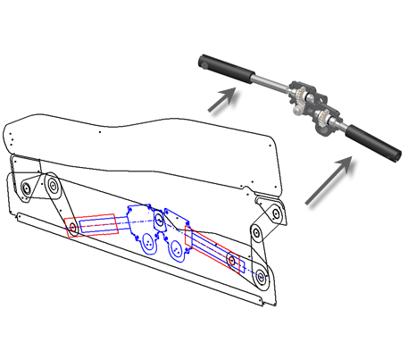
Once you have created your layout, you push-derive sketch block instances to component instances in part and assembly files. For Make Components, the shapes of component instances remain associated with the block instances in your layout. As a result, changes you make to block definition shapes are reflected in your part and assembly files. If you change sketch constraints in your layout and want the new behavior reflected in component instances, you repeat Make Components for the affected components. The assembly constraints are updated accordingly. For Make Part, the shape and position of a component instance remain associated with the block instances in your layout. If you change shape or position of your block instances, the part file reflects the changes.
Once you have created your layout, you push-derive sketch block instances to component instances in part files. For Make Part, the shape and position of a component instance remain associated with the block instances in your layout. If you change shape or position of your block instances, the part file reflects the changes.
Use Make Components to create multiple new part and assembly files, or Make Part to create a single part file. Options are available for you to customize your Make Components process and you can set the default Make Components Options.
Use Make Part to create a single part file.
Layout part and Layout constraints
- In target assembly files, a layout part is created to which component instances (part and subassembly) are constrained. The layout part contains your layout sketch and, along with the Layout constraint, drives associativity between the component instances and your layout. By default, the layout part is invisible.
- In subassembly files, created from nested blocks in the master layout sketch, a layout part is also created to which component instances are constrained. In this case, the layout part manages the relationships between the children of the nested block. The component instances correspond to the children of the nested block and the subassembly corresponds to the parent of the nested block . By default, the layout part is invisible.
- Layout constraints are created and shown in the browser. The Layout constraint is comprised of flush constraints between the three primary planes of the layout and derived parts, and a zero degree angle constraint between the Z axes of the layout and derived parts. A context menu, Layout Constraint, is available when selecting a component. You use the menu position options to control the behavior of the component by suppressing or enabling child constraints of the Layout constraint.
-
- When Constrain to Layout Plane is on, the flush constraint associated with the layout plane (XY) is active and the Z axis angle constraint is suppressed. This restricts movement of the component instance to the layout plane.
- When Constrain to Layout Plane is off, the flush constraints are suppressed and the angle constraint between the Z axes is enabled. It restricts motion of the component instance parallel to the layout plane, but the instance can be dragged or offset from the layout plane.
For example, with the position option Assembly Controls Position (2D) enabled:
- Assembly constraints are created when the Make Components position option Create equivalent assembly constraints is set. These constraints correspond to geometric constraints between the sketch block instances.
The Make Components workflow maintains associativity between a block and component instance relative to shape. But it isolates the component instance from positional changes of the block in your layout. You realize a significant benefit from this functionality when your designs are coordinated with a data management system.
For example, say that you have a large assembly represented by your layout. You have created multiple part files from block instances in your layout using Make Components. You then decide to change the position of several block instances in your layout, but not their shape. Since the position of a block instance does not affect the associated component instance, your documents that detail the design of the component instance are not affected. As a result, you avoid unnecessary revisions to design documents in your data management system. Note that any design documents that involve the position of the component, such as assembly drawings in which the component occurs, would require revision.
The ability to isolate shape from position relies on the use of a layout part and Layout constraint. A layout part and Layout constraint are created in assemblies in which your new component is instanced. The layout part contains your layout sketch and reflects any changes to the layout. The Layout constraint positions the component instance relative to the layout part. As a result, positional changes of block instances in your layout are reflected in the assembly, but the actual design (shape) of a component instance is not affected.
Model browsers for assembly files created by the Make Components process display a few notable items:
Multi-body parts
In certain design situations, it is effective to use a multi-body part, rather than a layout sketch, to drive your top-down design workflow. Essentially, you treat the multi-body part as a layout, but in the part modeling environment. You create and position multiple solid bodies in the single part file to achieve your design. Then, you push derive the solid bodies to part files and place them in your target assembly.
In certain design situations, it is effective to use a multi-body part, rather than a layout sketch, to drive your top-down design workflow. Essentially, you treat the multi-body part as a layout, but in the part modeling environment. You create and position multiple solid bodies in the single part file to achieve your design. Then, you push derive the solid bodies to part files.

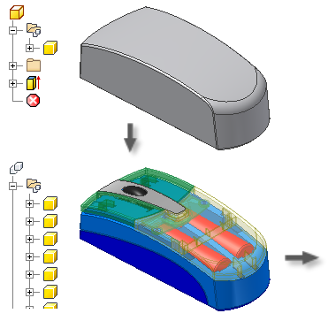
Component design that involves complex shapes across multiple parts is a prime example of when multi-body parts are useful in top-down design. Take your standard computer mouse. The mouse typically has multiple plastic parts that share complex curves and surfaces. If you use a layout and sketch blocks to represent the mouse, it is difficult to communicate the complex curves and surfaces to the constituent parts in a top-down fashion. If you use a multi-body part, you initially create the entire mouse as a single solid and manipulate the solid into the desired shape. Then, you separate the single solid into multiple solid bodies that represent such items as the mouse buttons and housing. You use Make Part or Make Components to derive the solid bodies to part files in your target assembly. The part files remain associated to your multi-body part such that any changes are reflected in the new files.
Component design that involves complex shapes across multiple parts is a prime example of when multi-body parts are useful in top-down design. Take your standard computer mouse. The mouse typically has multiple plastic parts that share complex curves and surfaces. If you use a layout and sketch blocks to represent the mouse, it is difficult to communicate the complex curves and surfaces to the constituent parts in a top-down fashion. If you use a multi-body part, you initially create the entire mouse as a single solid and manipulate the solid into the desired shape. Then, you separate the single solid into multiple solid bodies that represent such items as the mouse buttons and housing. You use Make Part to derive the solid bodies to part file. The part file remains associated to your multi-body part such that any changes are reflected in the new file.
Learn more about Multi-body parts.