Inventor Studio is a rendering and animation environment within Autodesk Inventor parts. This environment has its own set of commands and unique browser nodes specifically for rendering and animating. Use the slow double-click method to rename Studio browser nodes, in the Animation browser. Both browsers stay in sync and reflect the name changes.
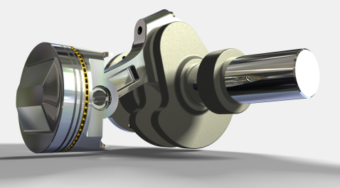
- Create still and animated renderings of parts and assemblies to visualize the appearance and motion of a design before it is built.
- Create still and animated renderings of parts to visualize the appearance and motion of a design before it is built.
- Compose a video using one or more cameras from one or more animations within the same part or assembly.
- Compose a video using one or more cameras from one or more animations within the same part.
- Create and save multiple animations in one assembly file or a part file.
- Create and save multiple animations in a part file.
- Reuse constraints or parameters between animations in one assembly file.
- Reuse parameters between animations in one part file.
- Reuse position values for the target and camera locations, and copy cameras within a document or into documents that have the Studio environment active.
- Use Select Top-Level Constraints to select all constraints at a specific assembly level and below. You can add selected constraints to the animation favorites or suppress them, in one action.
- Use Select All Constraints to add all constraints in the assembly to the Animation Favorites folder or suppress them, in one action.
The rendering and animation environment updates with subsequent changes you make in the part or assembly file.
Rendering and animation files update with subsequent changes you make in the part file.
When you enter the Studio environment for the first time, the active Model State and representations are the starting condition for rendering or animation. This condition is named Original State in the Animations browser folder. Before you enter the Studio environment, activate the desired Model State and representations to define the Original State. All animations use the Original State for animation frame zero.
Animation cannot be performed in the Original State, however, you can edit camera, lights, and other rendering properties. Changes to the model outside of Studio effect the Original State and so can change how each animation begins. To work in an animation, activate an animation either by selecting it and using the context menu command, or by double-clicking the animation node icon. Switch between animation and Original State by double-clicking the appropriate browser node.
Rendering and animation commands
Commands for rendering and animation are available on the Render tab. The appropriate dialog box opens when you activate a command. Click the pin in the upper-right corner to roll up the dialog boxes.
Options for actions in the browser and graphics area are available on context menus.
Rendering process
You can run the rendering command with no enhancements to the geometry you obtain directly from Autodesk Inventor parts and assemblies, or you can assign lighting styles and camera viewpoints that provide visual interest and a sense of scale or space in the rendering.
You can run the rendering command with no enhancements to the geometry you obtain directly from Autodesk Inventor parts, or you can add lighting and camera viewpoints that provide visual interest and a sense of scale or space in the rendering.
Rendering commands are available on the Render tab, and on context menus in the graphics area.
Adjust Global options such as anti-aliasing quality, output resolution, and geometry detail, that are not specific to particular lights or geometry, to control the appearance and performance of the rendered image. A good thing to remember is image size and machine performance are linked. Creating larger size images requires more machine resources and more time. The same is true of video output.
The rendering progress is displayed in a separate window. You can save rendered output to standard formats: .bmp, .gif, .jpg, .jpeg, .tif, .tiff, and .png. Each image format, except .gif, have options when saving, such as dpi, quality, or alpha channel. Look through the options when saving so you can use the format best suited for post processing if such is planned.
Anti-aliasing options
There are five anti-alias filters available - Box, Triangle, Gaussian, Lanczos, and Mitchell. The following images are examples of each. Render time: .5 minutes, anti-alias filter using default value.
| Image Filter | Example |
|---|---|
| Box | 
|
| Triangle | 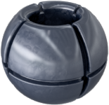
|
| Gaussian | 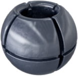
|
| Lanczos | 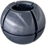
|
| Mitchell | 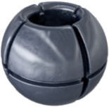
|
Styles available for rendering and animation
A set of predefined Lighting Styles are installed as libraries with Studio. You can create and save your own styles in the libraries. Styles are imported into a part or assembly document library, and are displayed in the styles list of the corresponding dialog box.
A set of predefined Lighting Styles are installed as libraries with Studio. You can create and save your own styles in the libraries. Styles are imported into a part document library, and are displayed in the styles list of the corresponding dialog box.
Materials and Appearances access
Material and Appearance Libraries are installed with the product or suites. Materials and Appearances are accessed from the Tools tab, in the Material and Appearance panel and from the QAT. See Materials and Appearances for more information.
Kinds of animations to create
You can create animations of:
- Rotation, as on a turntable, as a function of a camera or a model.
- Mechanistic movements of a model based on assembly constraints.
- Positional representations created and saved in the assembly environment.
- Product fly-bys using the Animate Camera Path method.
- Specialized lighting effects by animating light styles or individual lights.
- Composited animations using Video Producer.
Influences on rendering time of animation
There are various aspects of lighting, surface texturing, and other cases that affect the rendering time for animations. The following table is a list of those cases that most often affect the rendering time. Combining cases can compound the impact on render time. We recommend previewing renders and using the appropriate lighting style and material appearances for the final renders.
 |
CPU, Multi-processor, or multi-core, performance |
The Translating phase is not multithreaded and benefits from a faster CPU, but not from more cores. The Computing and Rendering phases are multithreaded. While these phases benefit from a faster CPU, they also benefit almost linearly from more cores. For example, Rendering is almost twice as fast with two cores. There is no practical limit on the number of cores that Inventor Studio can use. |
 |
RAM |
Rendering requires a copy of the scene for use by the rendering engine. This copy is made for every frame, which is the purpose of the Translating phase. The memory consumed by this copy is in addition to whatever memory Inventor uses on its own. Therefore, you must have spare physical RAM available, before rendering, to successfully and efficiently render. When the OS runs out of physical RAM, disk swapping can occur, or rendering becomes incredibly slow and unusable. Inventor provides tools, such as simplification, that help with memory consumption. Learn to use the tools in order to make more memory available for processes like rendering. |
 |
GPU or Video card | The GPU (graphics card or chipset) has absolutely no impact on rendering performance or capacity. |
 |
Quantity and type of lights used |
The number, types of lights, and their settings effects render times. When you have more than one light casting shadows, the render time effected since shadows for every object the light shines on must be computed. |
 |
Soft Shadows |
Render times increase when you use soft shadows with a medium or high Quality setting. |
 |
Transparent components |
Transparent components with refraction settings greater than 1.0 contribute to render time. |
 |
Bump maps |
Bump maps make textures look more realistic by causing a faux surface irregularity. Bump maps contribute to render times. Consider assigning bump map textures for the final render. Assigns the selected material to the selected surfaces, the same as using the Appearance drop-down list on the Autodesk Inventor Quick Access toolbar. Available if material is selected in the tree and one or more surfaces are selected. |
 |
Refraction |
When multiple components with refractive appearances overlap in the rendered scene, more render time is required since many rays must be traced for each pixel in the overlap. When multiple objects with refractive appearances overlap in the rendered scene, more render time is required since many rays must be traced for each pixel in the overlap. |
 |
Video effects |
Video effects, such as fades and gradient wipes, require rendering cells from the two contributing shot footages. When transitions are used, the rendering time doubles for that transition time. |
 |
Depth of Field |
Enabling the depth of field option on cameras increases rendering time by about 4X due to the multiple passes required to render the scene. Enabling the depth of field option introduces high-frequency noise in out-of-focus areas. Increasing image antialiasing smooths out this noise, but increases the rendering time further still. |
|
|
Animations |
Rendering successive frames is neither faster nor slower than rendering one frame at a time. For example, if it takes 5 minutes to render one frame, it takes about 12 hours to render a ten-second animation at 15 fps, because 150 frames X 5 minutes (per frame) = 750 minutes. Assuming the content of the rendered scene does not change, memory consumption should not climb as an animation is rendered, that is, if you can render one frame, render as many as you want for an animation without running out of memory. If that is not the case, there may be another issue, and a support issue should be logged with Autodesk. |
 |
Inventor Studio Requirements |
Determine accurate requirements by testing your assemblies and your hardware. Determine accurate requirements by testing your parts and your hardware. However, as a rule of thumb, consider these options:
|
Animation process
- Plan your animation. Start with a purpose, for example, demonstrating the use of a product.
- Outline the product features you want to highlight in the animation.
- Open the component or wrapper assembly and set up the camera positions.
- Open the part and set up the camera positions.
- Use the various Studio commands to define the appearance of components and props.
- Use the Studio commands to create the animation steps.
- Analyze and refine the various features until you are satisfied with the result.
- Finally, render it.
Animation commands are available when an animation is active. The commands are on both the Render tab and context menus in the graphics area.
Parameter Favorites provides access to the user parameters in the active file, and a means to add them to the Animations Favorites folder in the browser.
Animation Timeline specifies the timing of all the actions in an animation, and controls playback.
An action is a transition to a specific value for a property from the previous value. Each action has a specific start and end time. If the action has no duration, the action value is assumed immediately at the action time, without interpolation.
You can copy and paste animation actions of the same type into the timeline at another time location.
Animate Components is for component transformation and rotation. You can select components before you activate the Animate Components command, or use the transform triad on the cursor to select components after you activate the command.
Animate Fade controls the opacity of a component during a given time frame.
Animate Constraints specifies the value for modifying a constraint. Uses and defines linear or angular values. You can suppress constraints as an action.
Animate Parameters modifies the values of one or more user parameters in the current document or any documents referenced by subassemblies resulting in component animation.
Animate Parameters modifies the values of one or more user parameters in the current document.
Animate Camera specifies the camera animation parameters. Use the Turntable or Path options to create a product visualization animation quickly or the Path option to animate the camera for a fly-by of your product.
Animate Lights specifies the light style or light animation parameters. Create specialized lighting conditions and animate them at specified times.
Render Animation renders an animation with one image for each frame of animation, with the frames saved in a single video file or separate image files.
Animate PR animates positional representations that you create in the assembly environment.
Animation Favorites
The Animation Favorites folder is visible in the browser in the Studio environment. The folder is populated by constraints and parameters used in the animation or the parameters nominated by you, from the model parameters, using the process described in the following section. Animation Favorites provide a means to add an action to an already animated constraint or parameter. They also provide the means to split an animation action in two.
The Animation Favorites folder is visible in the browser in the Studio environment. The folder is populated by parameters used in the animation or the parameters nominated by you using the process described in the following section. Animation Favorites provide a means to add an action to an already animated parameter. They also provide the means to split an animation action in two.
For example, consider a mate constraint that is animated with a starting value of 0.0 in and an ending value of 6.0 in. The action has a duration from 0.0 seconds to 3.0 seconds. Placing the timeline slider at 2.0 seconds and double-clicking the constraint brings up the constraint mini-dialog box (also referred to as a torpedo dialog box). The dialog box displays 4.0 in. If the value is edited and changed, the existing action is terminated at the selected time position with the new constraint value. In this example, the action now occurs from 0.0 to 2.0 and uses the values 0.0 to 4.0 for that time period. A second action is created from 2.0 to 3.0 time period with values of 4.0 to 6.0 (start to end).
To include a model parameter or constraint in the Favorites folder do one of the following actions:
To include a model parameter in the Favorites folder do one of the following actions:
- Click Parameter Favorites. In the dialog box, check the parameters you want to animate and OK.
- Animate a constraint or parameter that is not already in the folder. It is added to the folder automatically.
- Animate a parameter that is not already in the folder. It is added to the folder automatically.
- In the Parameters dialog box, specify animation favorites.
How animations differ from presentations in Autodesk Inventor
The animation environment results in mechanistic movement according to the application of constraints, and provides high-quality output. The presentation environment is designed for documenting exploded views.
|
Animation environment |
Presentation environment |
|
|
Assembly model |
Stored in assembly model. Move between assembly and animation freely. |
Separate file and extension. |
|
Constraints |
Honors assembly constraints. Used to solve for movement. Can be animated or suppressed. |
Used only for automatic explode; otherwise has no influence in creating an animation. |
|
User parameters |
Can be animated. |
Cannot be animated. |
|
Rendering environment |
Integrated part of environment. |
No rendered output. |
|
Camera control and animation |
No limit on the number of cameras, and can animate in scene. |
No user-defined cameras. Can animate default camera between positions. |
|
Composite animation output |
Combine multiple animation sequences and render with scene transitions |
Single-stream animation output. |
|
Animate Lighting |
Lighting styles, individual lights can be animated. |
No Light animation. |