What's New: 2022
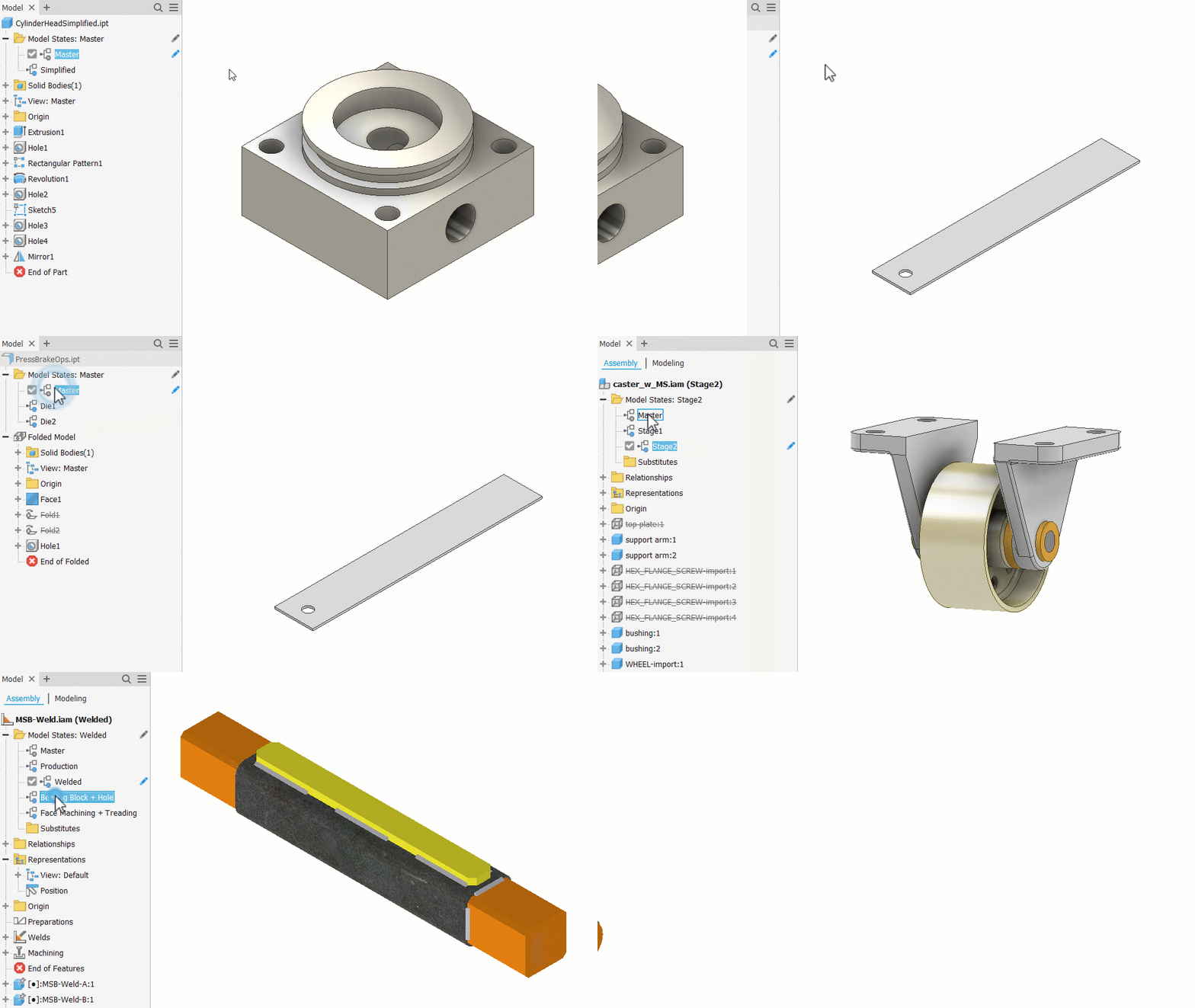
Use Model States to represent your designs at different sizes, manufacturing stages, and simplification levels in a single part or assembly file. Each member can have their own parameters, iProperties and BOM information.

The first entry in both Part and Assembly Model States is named Master. Master can be modified as desired like other model states. Master cannot be renamed, reordered, or deleted.
Model States in drawings
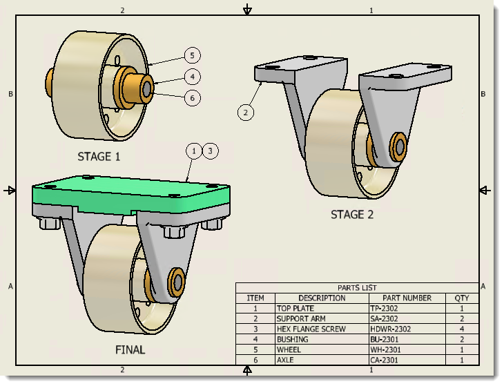
You can select a model state when creating a drawing view. Each model state can have unique members and iProperties. A view created from a Substitute model state reflects the state of the substitute part in the drawing view.
You can also select Design View and Positional representations, so that the combination is represented in the view.
After the view is created, you can edit it to change to a different representation, if appropriate.

Model States in presentations
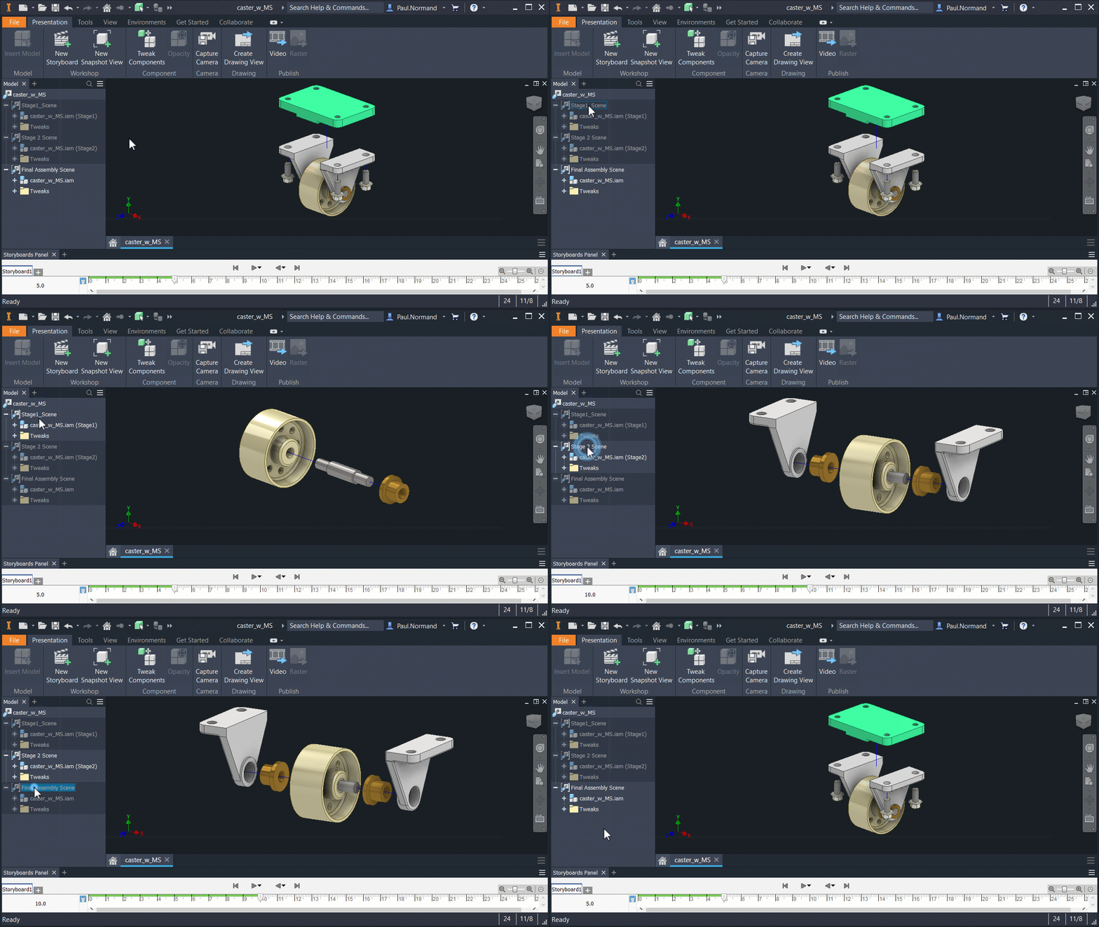
Like drawings and other assemblies, presentations use specified Model States.
In the assembly, create a model state entry and save the file. In a new presentation file, use Insert Model and browse to the appropriate assembly. Use Options to specify the appropriate model state.
Further, a presentation updates to reflect changes in the model state. For example, if you add tweaks in a presentation, and then edit the model state in the assembly to suppress more parts, when you return to the presentation, it shows the new state. If parts were deleted that participated in a tweak, the tweaks are deleted.

Use View and Positional representations with Model States
Model States, View, and Positional representations can be used together. Adjusting one type of the representations does not alter the others.
Work with the Bill of Materials
Each model state supports unique iProperties, Parameters, and Bill of Materials. You can also add a Model State column that lists the model state of components in the assembly.
- Suppressed components do not participate in the Bill of Materials
- A Substitute model state balloons as a single part.
- The model state is a migrated non-Master Level of Detail.
- The model state is a migrated or new substitute.
Publish DWF data
The published file represents the active model state. Activate the appropriate model state in the browser and then use File  Publish or File
  Save Copy As. Specify the DWF file type and desired options.
Solving constraints
Some constraints may be affected by component suppression. For example, transitional constraints cannot be solved if a component is suppressed, but rotational and other types of constraints are not affected.
Suppressed components are not adaptive.
Create a simplified model state
Create a model state in a part file and suppress features to create a simplified model. This can be useful for simulation and analysis purposes.

Create a substitute model state in an assembly to use a part file in place of the assembly using one of the following techniques:
- Use Simplify to create a substitute part file. A single surface composite feature creates the smallest file.
- Use Derive Assembly to create a derived part from the assembly to use as a substitute.
- Create a new part file that represents a simplified version of the assembly to use as a substitute model state.
