What's New: 2020.1
By default, parts are created at the root level of the assembly
 . To create parts in a sub-assembly, click the toggle.
Calculate linear cams
|
|
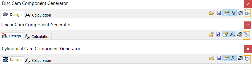
- On the ribbon, click
Design tab
 Power Transmission panel
Linear Cam .
Power Transmission panel
Linear Cam .
- On the Design tab:
- On the Cam group box, select which type of cam you want to insert (Component, No Model).
- Insert values for cam and follower.
- Switch to the Calculation tab:
- Enter the calculation values. You can change the values and units directly in the edit fields.
- Click Calculate to perform the calculation.
- Calculation results are displayed in the Results area. The inputs that fail the calculation are displayed in red (their value does not correspond with other inserted values or calculation criteria). Reports of the calculation are displayed in the Summary of Messages area which is displayed after clicking on the chevron in the right lower part of the Calculation tab.
- (Optional) Click
 Save to file above the graph area to save graph data to the text file. Save to file above the graph area to save graph data to the text file.
- (Optional) Click
 Results in the upper-right corner of the Design or Calculation tab to open HTML report. Results in the upper-right corner of the Design or Calculation tab to open HTML report.
- If calculation indicates design compliance, click OK.
|
Edit linear cams
|
|
- Open the
Autodesk Inventor assembly with the already inserted Design Accelerator linear cam.
- Select the linear cam, right-click and select the Edit Using Design Accelerator command.
- Edit the cam. You can change the type of cam (Component, No Model) or recalculate values. If you changed calculation values, click Calculate to see strength check and geometric calculation. Calculation results are displayed in the Results area. The inputs that fail the calculation are displayed in red (their value does not correspond with other inserted values or calculation criteria). Reports of the calculation are displayed in the Summary of Messages area which is displayed after clicking on the chevron in the right lower part of the Calculation tab.
- Click OK.
|
 Cam Tutorial