You can define constraint pairs in components, called iMates, that tell parts and subassemblies how to connect when inserted in an assembly. You can also define one half of the constraint pair limits to specify the allowable range of motion. Symbols identify iMates. The symbols show the type and state of the iMate.
You can define constraint pairs in components, called iMates, that tell components how to connect when inserted in an assembly. You can also define one half of the constraint pair limits to specify the allowable range of motion. Symbols identify iMates. The symbols show the type and state of the iMate.
You can define groups of iMates, called composite iMates. When placed and matched with another composite iMate with the same name and number of members, all constraints in the group are solved.
Creating iMates
You create iMates as you create or modify a component or by inferring them automatically. You define half of a constraint pair on a component. The iMate definition is stored in the file, and when the component is placed in an assembly, it is automatically positioned (the iMate result ).
You create iMates as you create or modify a component or by inferring them automatically. You define half of a constraint pair on a component. The iMate definition is stored in the file, and when the component is placed in an assembly, it is automatically positioned.
On the ribbon, use
Manage tab  Author panel
iMate to define an iMate when creating or modifying a component. Or, use the Infer iMates check box when creating or editing hole features or extrude and revolve features with closed-loop circular edges.
Author panel
iMate to define an iMate when creating or modifying a component. Or, use the Infer iMates check box when creating or editing hole features or extrude and revolve features with closed-loop circular edges.
You can select two or more iMates in the browser, and then right-click to create a composite iMate. When placed in an assembly, all constraints are satisfied when matched to a component with a matching composite iMate.
To convert existing assembly constraints to iMate definitions, right-click a constraint in the browser and select Infer iMates. You can create individual iMates or composite iMates.
Inferred iMate definitions are saved with the component. The iMates created with this method do not replace the constraints that were originally placed in the active assembly. To replace original constraints with new iMates, manually delete the constraints and apply new iMates.
Inferred iMate definitions are saved with the part.
What are inferred iMates?
An inferred iMate is automatically calculated based on a special algorithm that places the constraint in a location likely to be the most useful.
In an assembly, iMates can be inferred on selected components, features, or constraints.
You can infer iMates on a closed-loop circular edge for extruded, revolved, and hole features. When you create the feature, select the Infer iMate check box to create an iMate automatically. For example, one or more insert iMates can be inferred for a hole or a revolve feature.
Or, right-click a feature in the browser and select Infer iMate. You can give the iMate a name or accept the default name.
Use infer iMates on a constraint when you have multiple components that must constrain to multiple instances of the same part in an assembly file.
Use infer iMates on a constraint when you have multiple components that must constrain to multiple instances of the same component in an assembly.
You create or infer iMates when you want geometry to use in assembly constraints. iMates also document the way you intend components to relate to one another. For example, the four mounting holes and the shaft of a motor can all have iMates. They identify the geometry that is likely to be constrained when the motor is placed in an assembly. The same iMates also serve to document the interface of the motor. It has a mounting interface (the four iMates on the holes) and a drive interface (the iMate on the shaft that rotates). You can also create iMates on the electrical connectors on the motor to represent the electrical interface.
You create or infer iMates when you want geometry to use in assembly constraints. iMates also document the way you intend components to relate to one another when placed in an assembly. For instance, you can create iMates on electrical connectors to represent the electrical interface in an assembly.
How do iMates differ from assembly constraints?
You define iMates when you create or edit a component, attaching them to critical placement features. Components that constrain to one another in an assembly each have one half of an iMate pair. When the components are placed in an assembly, the iMate halves know how to fit together.
You can retain constraints during component replacement by using matching iMates in both components. The components with the matching iMate definitions match so long as their properties match, not necessarily their geometric shape. For example, if their properties are the identical, an insert iMate definition can be equivalent on a circular edge and a circular arc.
You define assembly constraints when you place a component in an assembly and match its position relative to another component. A component replacement without iMates retains assembly constraints only if the existing and new components are created from a common base (using Save Copy As). Unless you use iMates each time you use a component, define how it fits together with other components.
Using iMates in an assembly
iMates are ideal for components that are used repeatedly and always constrained in the same way. You define an iMate once, saving time every time you place the component. Composite iMates solve multiple constraints with a single selection.
Using iMates, you can automatically place key assembly constraints when you place the component:
- On the placed component, an iMate definition is matched based on its properties. If the iMate definition names and match lists do not match, the iMate definitions can still match. However, pairings of iMate definitions whose names and match lists do match are preferred over definitions that do not.
- When the two iMate halves match in the assembly, a single consumed iMate result is created.
An iMate symbol is shown in the browser and on the components in the graphics window (although they are off by default). On the ribbon, use
View tab
Visibility panel
iMate Glyphs option to control the display of iMate glyphs in the graphics window.
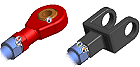
In the illustration, the rod and the housings have iMates with the same name. Multiple housings can have the same relationship defined as an iMate. You can use Replace Component to switch housings and retain the constraint relationship between the rod and housing.
A composite iMate definition can include multiple iMate definitions. It could, for example, set an offset distance, an insert axis, mating faces, and a range of motion. When placed in an assembly, all constraints are satisfied when matched to a component with a composite iMate definition with the same number of members with matching properties. The composite iMate definitions whose names and match lists do match are preferred over definitions that do not.
Combining iMates in composite
In the browser, you can select two or more iMates, right-click, and then select Create Composite. A composite iMate is created in the browser with the individual iMates nested under it. You can use the default composite name or give it a more meaningful one.
In other parts that use the same iMate combination, create another composite iMate containing the same individual iMates. When matched with another composite iMate with the same name and number of members in an assembly, all constraints are solved at once.