Create rectangular, circular, mirror, and patterns along a path.
What's New: 2020.1
Arrange Part Features or Bodies in a Rectangular or Other Pattern
The Rectangular Pattern tool duplicates features or bodies and arranges the results in a rectangular pattern, along a path, or bidirectionally from the original feature.
- Click
3D Model tab
 Pattern panel
Rectangular Pattern
Pattern panel
Rectangular Pattern
 .
.
- In the Rectangular Pattern dialog box, specify what you want to pattern:
- Pattern Individual Features
 . Patterns individual solid features, work features, and surface features. Cannot pattern assembly work features.
- Pattern a Solid
 . Patterns a solid body, including features that you cannot pattern individually. Can also include work features and surface features. Not available in an assembly.
- Pattern Individual Features
- In the graphics window or in the browser, select one or more features or bodies to include in the pattern. For parts, you can also select work features and surface features to include in the pattern.
- In a multi-body part, use the Solid selector
 to choose the solid body to receive the pattern.
- Align selected features in a pattern of rows and columns by specifying the following:
Note: When a work plane or planar face is selected, the normal of the plane is the linear direction.
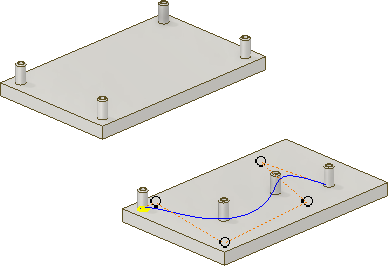
- Path
 . Selects the direction in which to add occurrences. Direction arrow originates at the selection point. Path can be a 2D or 3D line, arc, spline, trimmed ellipse, or edge. Path can be an open or closed loop.
- Flip
 . Reverses direction of occurrences. If you select Midplane and the occurrence count is even, indicates which side gets the extra occurrence.
- Midplane
 . Creates a pattern where the occurrences are distributed on both sides of the original feature. For rectangular patterns, you can use Midplane independently for either direction (Direction 1, Direction 2).
- Count
 . Specifies the number of occurrences in the column or linear path. Must be greater than zero.
- Length
 . Specifies spacing or distance between occurrences or distance the column or row spans. A negative value can be entered to create a pattern in the opposite direction.
- Distance, Spacing, or Curve Length. Specifies how Length is measured: The total distance of the column or row, the amount of spacing between occurrences, or equally fitted to the length of the selected curve. Must be greater than zero.
- Path
- If patterning a solid, choose an operation:
- Join
 . Attaches the pattern to the selected solid body. Patterns the solid as a single, unified body.
- Create New Bodies
 . Creates a pattern consisting of multiple individual solid bodies.
- Join
- Click More
 to set the direction start points, the compute method, and the orientation of the patterned features:
Direction 1 and Direction 2
to set the direction start points, the compute method, and the orientation of the patterned features:
Direction 1 and Direction 2- Start. Sets the start point for the first occurrence in both directions. If appropriate, pattern can start at any selectable point. Click Start and then, to indicate the start of one or both columns, click a point on the path. If path is a closed loop, it requires a start point.
Compute- Optimized. Creates identical copies of selected features by patterning feature faces. Optimized is the fastest compute method. Limitations are the inability to create overlapping occurrences, or occurrences that intersect different faces than the faces of the original features. When possible, speeds up the pattern compute.
- Identical. Creates identical copies of selected features by replicating the results of original features. When the Optimized method is not possible, use for identical features.
- Adjust. Creates potentially differing copies of selected features by patterning features and calculating extents or terminations of each pattern occurrence individually. Computation time is lengthy for patterns with large numbers of occurrences. Preserves design intent by allowing pattern occurrences to adjust based on feature extent or termination conditions, such as a feature that terminates on a model face. Not available for patterns of solid part bodies in an open or surface state.
Note: Patterns created with the Optimized or Identical method calculate faster than the Adjust method. If Adjust encounters a planar face, the pattern terminates. Results are a feature with a size and shape different from the original.Orientation- Identical. Each occurrence in the pattern is oriented the same as the first selected feature.
- Direction1 or Direction 2. Specifies which direction controls the position of patterned features. Rotates each occurrence so that it maintains its orientation to the 2D tangent vector of the path, based on the first selected feature. The angle exaggerates with each occurrence in the pattern. For best results, place the first occurrence on the start point of the path.
- Click OK.
Arrange Part Features or Bodies in a Circular Pattern
The Circular Pattern command arranges occurrences of selected features or bodies into an arc or circular pattern. It duplicates one or more features or bodies and arranges the resulting occurrences by a specific count and spacing in an arc or circle.
- Click
3D Model tab
Pattern panel
Circular Pattern
 .
.
- In the Circular Pattern dialog box, specify what you want to pattern:
- Pattern Individual Features
. Patterns individual solid features, work features, and surface features. Cannot pattern assembly work features.
- Pattern a Solid
. Patterns a solid body, including features that you cannot pattern individually. Can also include work features and surface features. Not available in an assembly.
- Pattern Individual Features
- In the graphics window or in the browser, select one or more features or bodies to include in the pattern. For parts, you can also select work features and surface features to include in the pattern.
- In a multibody part, use the Solid selector
to choose the solid body to receive the pattern.
- Click the Rotation Axis selector
and select the axis (pivot point of angle) about which occurrences should repeat. The axis can be on a different plane from the feature being patterned. Click Flip to reverse the direction of the pattern.
- Specify Placement options:
- Count
. Specifies the number of occurrences in the pattern.
- Angle
 . Angular spacing between occurrences depends on the positioning method. If you select Incremental positioning, the angle specifies the angular spacing between occurrences. If you choose Fitted positioning, the angle specifies the total area the pattern occupies. Enter a negative value to create a pattern in the opposite direction.
- Midplane
 . Distributes the feature occurrences on both sides of the original feature, which is typically created in a centered location. When the occurrence count is even, use Flip to determine which side gets the extra occurrence.
- Count
- If patterning a solid, choose an operation:
- Join
. Attaches the pattern to the selected solid body. Patterns the solid as a single, unified body.
- Create New Bodies
. Creates a pattern consisting of multiple individual solid bodies.
- Join
- Select one of the following Orientation options:
- Select Rotational
 if you want the body or feature set to change orientation as it moves around the axis.
- Select Fixed
 if you want the orientation of the body or feature set to be identical to the parent selection as it moves around the axis.
Optionally, select Base Point
 and then select a vertex or point to redefine the Fixed pattern base point.
- Select Rotational
- Click More to set the compute and positioning methods of the patterned features:
Creation Method
- Optimized. Creates identical copies of selected features by patterning feature faces. Optimized is the fastest compute method. Limitations are the inability to create overlapping occurrences, or occurrences that intersect different faces than the faces of the original features. When possible, speeds up the pattern compute.
- Identical. Creates identical copies of selected features by replicating the results of original features. Use for identical features when the Optimized method is not possible.
- Adjust. Creates potentially differing copies of selected features by patterning features and calculating extents or terminations of each pattern occurrence individually. Computation time is lengthy for patterns with large numbers of occurrences. Preserves design intent by allowing pattern occurrences to adjust based on feature extent or termination conditions, such as a feature that terminates on a model face. Not available for patterns of solid part bodies in an open or surface state.
Positioning Method- Incremental. Defines the spacing between features. You specify the number of occurrences in the pattern and the angle. The total area occupied by the pattern is calculated.
- Fitted. Uses an angle to define the total area the patterned features cover. You specify the number of occurrences and the total angle. Spacing between occurrences is calculated. If the design is likely to change, use Fitted positioning, because the spacing of occurrences updates according to design intent.
- Click OK.
Pattern Part Features or Bodies on Sketch Points
The Sketch Driven Pattern command arranges occurrences of a feature or body on 2D or 3D sketch points. It duplicates one or more features or bodies and arranges the resulting occurrences in a pattern defined by the sketch points.
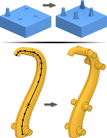
- Create sketch points in a 2D or 3D sketch on your model and arrange them in the required pattern.
- Click
3D Model tab
Pattern panel
Sketch Driven
 .
.
- In the Sketch Driven Pattern dialog box, specify what you want to pattern:
- Pattern Individual Features
. Patterns individual solid features, work features, and surface features. Cannot pattern assembly work features.
- Pattern a Solid
. Patterns a solid body, including features that you cannot pattern individually. Can also include work features and surface features. Not available in an assembly.
- Pattern Individual Features
- In the graphics window or in the browser, select one or more features or bodies to include in the pattern. For parts, you can also select work features and surface features to include in the pattern.
- In a multibody part, use the Solid selector
to choose the solid body to receive the pattern.
- If there is more than one sketch or the sketch is invisible, select the sketch to use.
- Optionally, do the following:
- Select Base Point and then pick a new reference point to use as the pattern Base Point.
- Select Faces and then pick a face to specify the face normal direction for the pattern.
- Click More to set the compute and positioning methods of the patterned features:
Creation Method
- Optimized. Creates identical copies of selected features by patterning feature faces. Optimized is the fastest compute method. Limitations are the inability to create overlapping occurrences, or occurrences that intersect different faces than the faces of the original features. When possible, speeds up the pattern compute.
- Identical. Creates identical copies of selected features by replicating the results of original features. Use for identical features when the Optimized method is not possible.
- Adjust. Creates potentially differing copies of selected features by patterning features and calculating extents or terminations of each pattern occurrence individually. Computation time is lengthy for patterns with large numbers of occurrences. Preserves design intent by allowing pattern occurrences to adjust based on feature extent or termination conditions, such as a feature that terminates on a model face.
- Click OK.
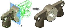
Arrange Part Features or Bodies in a Mirror Pattern
The Mirror command makes a reverse copy of one or more features, an entire solid, or a new body at equal distances across a plane. Use a workplane an existing planar face for the mirror plane.
- Do one of the following:
- In a part file, click
3D Model tab
Pattern panel
Mirror
 .
.
- In an assembly file, click
Assemble tab
Pattern panel
Mirror
 .
.
- In a part file, click
3D Model tab
- In the Mirror dialog box, specify what you want to mirror:
- Mirror Individual Features
. Selects solid features, work features, and surface features to mirror. If selected features have dependent features, they are automatically selected. In assemblies, you can mirror only sketched features. You cannot mirror:
- assembly work features.
- single sheet metal flange and contour flange features defined using multiple edges.
- features that operate on the entire body (all fillets, all rounds, shell).
- features based on the results of an intersect operation.
- Mirror a Solid
. Selects part bodies. Allows you to optionally include work and surface features in the selection.
- Mirror Individual Features
- In the graphics window or in the browser, select the feature or features to mirror.
- In the Mirror dialog box, click Mirror Plane and then select a workplane or planar face to use as the mirror plane. Use Mirror Component on the Assemble tab.
- In a multibody part, select Solid and then choose the solid body to receive the mirror feature.
- If mirroring a solid, choose an operation and decide if you want to remove the original:
- Join
. Joins the feature to the selected body.
- New Solid
. Creates a body in a multibody part.
- Remove Original. Removes the original body. Only the mirrored occurrence remains in the part file. Use to model a left and right version of a part.
- Join
- Click More
to specify how mirrored features are calculated:
- Optimized. Creates identical copies of selected features by mirroring feature faces. Optimized is the fastest compute method. But it presents some limitations, such as the inability to create overlapping occurrences, or occurrences that intersect different faces than the faces of the original features. Speeds up mirror compute.
- Identical. Creates identical copies of selected features by replicating the results of original features. When the optimized method is not possible, use Identical for identical features. Calculates faster than the Adjust method.
- Adjust. Creates potentially differing copies of selected features by mirroring features and calculating extents or terminations of each mirror occurrence individually. Computation time can be lengthy for patterns with large numbers of occurrences. Preserves design intent by allowing mirror occurrences to adjust based on feature extent or termination conditions, such as a mirrored feature that terminates on a model face. Not available for mirrors of solid part bodies in an open or surface state.
- Click OK.
Tip: To remove participants from a mirror, expand the feature in the browser, right-click, and choose Remove Participant.
Control Visibility of Features in Patterns
Temporarily suppress the display of work, solid, or surface features in a pattern. Features remain suppressed until you restore them.
- Do any of the following:
- To suppress or restore visibility of all occurrences of solid features in a pattern, select the pattern icon in the browser, right-click, and choose Suppress or Unsuppress Features.
- To suppress or restore visibility of an individual occurrence of a solid feature in a pattern, expand the pattern icon in the browser, select the occurrence, right-click, and choose Suppress, or Unsuppress.
Note: Note: Occurrences that are suppressed individually must be restored individually.
- To hide or restore visibility of all work features or surface features in all pattern occurrences, select the pattern icon in the browser, right-click, and choose Hide All Work Features, Show All Work Features, Hide All Surfaces, or Show All Surfaces.
- To hide or restore visibility of an individual work or surface feature in a pattern occurrence, expand the pattern icon in the browser, select the occurrence, right-click, and then switch on or off the Visibility option.
Control Opacity of Surface Features in Patterns
When you create a surface, it is transparent and is the same color as a workplane. Use the Transparency option to make surfaces opaque.
- Do either of the following:
- To control opacity of all surface features in all pattern occurrences, select the pattern icon in the browser, right-click, and choose All Surfaces Opaque or All Surfaces Transparent.
- To control opacity of an individual feature in a pattern occurrence, expand the pattern icon in the browser, then expand the occurrence icon. Select the feature, right-click, and switch on or off the Transparent option.
Editing a Pattern Feature
- In the graphics window or the browser, right-click the feature and choose Edit Feature. The feature dialog box displays.
- Change the pattern type, number, direction, or spacing.
- Click OK.