Learn about ways to move or rotate a component.
When you constrain or join assembly components to one another, you control their position. To move or rotate a component, either temporarily or permanently, use one of the following methods:
Free move
You can move a component to get a better view of its features or to analyze relationships. A free move is a temporary "get out of the way" move. You might want to move components to:
- Display relationship dependencies as an elastic band to analyze the relationships.
- See a face or feature on the selected component.
- See a face or feature on a part that is obscured by the selected component.
- Facilitate selection of a face or feature on a component by moving it to an uncluttered area of the screen.
A free move is convenient but it is temporary. The part snaps back to its constrained or joined position when you apply a new relationship or update or refresh the assembly.
Drag move
To see how a component moves, you can drag it (and all components connected to it). A drag move honors previously applied relationships. That is, the selected component and joined parts move together in their related positions.
A grounded component cannot be dragged to a different location. Components related to the grounded component remain in their joined positions at the new location.
You can click any component in the edit target (the file that contains edits) and drag it to a new location. If you select a component that is not a child of the edit target (a part in a subassembly), the component acts as a handle and drags the whole subassembly.
Rotated components in assemblies
The Orbit command in the Navigate panel of the View tab rotates the entire assembly. When you want to rotate a single component, use the Rotate command in the Position panel of the Assemble tab. Operation of both commands is the same.
Keep the following behaviors in mind when you rotate components:
- You can rotate a constrained component.
- When you update the assembly, the components constrained to the rotated component snap into their constrained positions. The rotated component determines the viewing orientation of the components.
- Unconstrained components remain in their rotated positions when you update the assembly.
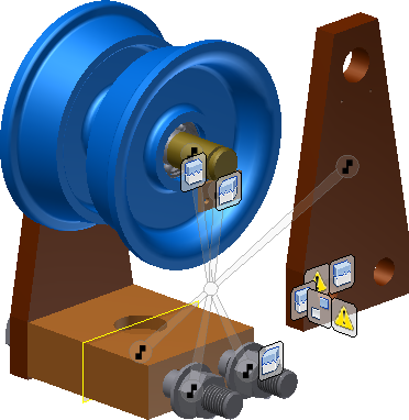
Grip Snap move and rotate
Use the Grip Snap command for precise movement or rotation of one or more assembly components, work geometry, or subassemblies. You control the Grip Snap command functions through the move options bar, the Heads Up Display (HUD), and the context menu.
After you apply a sequence of Grip Snap translations or rotations, you can select a new component as a new reference for a new sequence. The Grip Snap session remains active until you:
- Click Done to accept the actions previewed and end the Grip Snap session.
- Click Commit and Ground to accept and ground the entities you manipulated with the Grip Snap command and end the Grip Snap session.
Grip Snap move options
A set of icons represent the possible options for moving and rotating the particular entity you selected. The icon sets vary with different selections. The back button is always included so you can back out and deselect geometry while the command remains active.
A directional arrow is displayed on the graphic entity you select. A Flip option is available on the context menu so you can reverse the direction.
HUD (Heads Up Display)
The HUD provides feedback about geometry selections as you pass the cursor over them, and a box where you can enter precise values. The Display Degrees of Freedom option in the Grip Snap Options dialog box turns on translational and rotational degrees of freedom (DOF) information in the HUD for the active selection or cursor movement. Two icons added to the HUD represent translation and rotation, and their 2 fields contain numerical values that report associated degrees of freedom in a range from 3 to 0.
Addition options are available through:
- A context menu available during an active Grip Snap command, except when the move options bar is displayed.
- The Grip Snap Options dialog box, available on the context menu and in the Application Options
 General Tab, Grip Snap section.
Constraints
- Temporary constraints (TCs) are established between reference components or assemblies and other reference components or assemblies snapped together with the Grip Snap command.
- In Grip Snap, no lasting persisted constraint relationship is created for a TC.
- All the geometry in TCs is colored green, which remains visible if you manipulate it again. You can clear the snaps using the Clear Snaps option on the context menu.
- If you select a new component as a new reference for a new sequence in a Grip Snap session, the previous sequence is committed, and the TCs that were established are cleared.
- If you clear the snaps using the Clear Snaps option on the context menu, the TCs are also cleared and the Grip Snap session remains active.
- With Grip Snap, you can completely resolve all degrees of freedom for a given component or assembly, clear the TCs, and then continue to resolve degrees of freedom from the current transposition state.
Selection methods
- Pick geometry on a moveable object to select one or more components or work geometry as the basis for a translation or rotation.
- Use the CTRL key to add any number of components to a selection.
- Drag a window around the components to select.
- Select components in the browser instead of the graphics window using the CTRL key.
- Use a pre-defined selection filter available on the Select drop-down list, and then activate the Grip Snap command. You can add to the pre-defined selection with the CTRL key.
In Grip Snap operations, you can select any of the following in assembly components, work features, or subassemblies as the basis for a translation or rotation:
- Point (vertex, midpoint, center point, or work point origin)
- Line (linear edge, work axis, centerline, or ray origin)
- Circular edge or arc edge origin
- Circle vector
- Planar face (plane, work plane origin)
- Analytical Surface
- NURB Surface (non-rational B-spline surface)
Drive relationships
You can simulate mechanical motion by driving a relationship through a sequence of steps. After you have constrained or added a connection to a component, you can use the Drive relationship command to animate it by incrementally changing the value of the constraint. For example, you can rotate a component by driving an angular constraint from zero to 360 degrees. The Drive relationship command is limited to one relationship, but you can drive additional relationships by using the Equations command to create algebraic relationships between relationships.
You can also use Drive relationships to detect if components collide. When collision occurs, the motion stops, and you can adjust the component positions.