Transferred torque
where:
|
P |
power [kW] |
|
|
n |
speed [rpm] |
Calculation of Minimum Shaft Diameter
1. shaft inside diameter d h > 0
a) 
b) if d min ≤d h -> d min = 1.1 d h [mm]
c) if d min ≤ 1.5 d h -> d min = 1.5 d h [mm]
2. shaft inside diameter d h = 0
where:
|
d min |
minimal shaft diameter [mm] |
|
|
d h |
shaft inside diameter [mm] |
|
|
T |
torque [Nm] |
|
|
K a |
application factor |
|
|
K f |
fatigue-life factor |
|
|
S v |
desired safety |
|
|
τ A |
Allowable Shear Stress |
General calculation
|
|
the range of force activity on the shaft |
|
h k = h - h s - 2 s [mm] |
the range of force activity on the hub |
 |
shaft diameter of the range of the force activity |
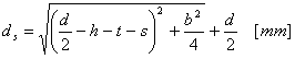 |
hub diameter of the range of the force activity |
|
|
force on shaft |
|
|
force on hub |
|
where: |
|
T |
torque [Nm] |
|
|
F s |
force on shaft [N] |
|
|
F h |
force on hub [N] |
|
|
K a |
application factor |
|
|
K f |
wear-life factor |
|
|
K w |
application factor |
|
|
K m |
load distribution factor |
|
|
S v |
desired safety |
|
|
d |
shaft diameter [mm] |
|
|
d s |
shaft diameter where force F s actuates [mm] |
|
|
d h |
shaft diameter where force F d actuates [mm] |
|
|
N |
number of grooves [-] |
|
|
h |
height of groove |
|
|
h s |
height of force point of action on shaft [mm] |
|
|
h h |
height of force point of action on hub [mm] |
|
|
b |
width of groove |
|
|
t |
groove depth in shaft [mm] |
|
|
s |
chamfer |
|
|
p Dmins |
minimal allowable pressure (groove, shaft) [MPa] |
|
|
p Dminh |
minimal allowable pressure (groove, hub) [MPa] |
Minimum key length to transfer the torque
|
1. Fixed connection: |
a) |
|
b) |
|
|
L min = min(L mins , L minh ) |
|
|
2. Flexible connection: |
a) |
|
b) |
|
|
L min = min(L mins , L minh ) |
|
|
where: |
|
F s |
force on shaft [N] |
|
|
F h |
force on hub [N] |
|
|
K a |
application factor |
|
|
K f |
wear-life factor |
|
|
K w |
application factor |
|
|
K m |
load distribution factor |
|
|
S v |
desired safety |
|
|
d |
shaft diameter [mm] |
|
|
N |
number of grooves [-] |
|
|
h s |
height of force point of action on shaft [mm] |
|
|
h h |
height of force point of action on hub [mm] |
|
|
p Dmins |
minimal allowable pressure (groove, shaft) [MPa] |
|
|
p Dminh |
minimal allowable pressure (groove, hub) [MPa] |
Minimal Allowable pressure
|
1. Fixed connection: |
a) |
|
b) |
|
|
2. Flexible connection: |
a) |
|
b) |
|
|
where: |
|
F s |
force on shaft [N] |
|
|
F h |
force on hub [N] |
|
|
K a |
application factor |
|
|
K f |
wear-life factor |
|
|
K w |
application factor |
|
|
K m |
load distribution factor |
|
|
S v |
desired safety |
|
|
d |
inside diameter of groove section [mm] |
|
|
N |
number of grooves [-] |
|
|
h s |
height of force point of action on shaft [mm] |
|
|
h h |
height of force point of action on hub [mm] |
|
|
l f |
active key length [mm] |
Strength Check
p mins ≤ p Ds
p minh ≤ p Dh
where:
|
p mins |
minimal calculated shear pressure in shaft [MPa] |
|
|
p minh |
minimal calculated shear pressure in hub [MPa] |
|
|
p Ds |
allowable pressure in shaft [Mpa] |
|
|
p Dh |
allowable pressure in hub [Mpa] |
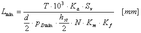
Simplified calculation
Minimum key length to transfer the torque
|
1. Fixed connection: |
 |
|
2. Flexible connection: |
 |
|
where: |
|
T |
torque [Nm] |
|
|
K a |
application factor |
|
|
K f |
wear-life factor |
|
|
K w |
application factor |
|
|
K m |
load distribution factor |
|
|
S v |
desired safety |
|
|
d |
shaft diameter [mm] |
|
|
N |
number of grooves [-] |
|
|
h |
height of groove |
|
|
s |
chamfer |
|
|
h st |
connection height h st = h - 2 s [mm] |
|
|
p Dmin |
allowable pressure on supporting surface of shaft, groove, or hub [MPa] |
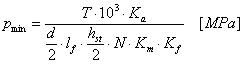
Allowable pressure
|
1. Fixed connection: |
 |
|
2. Flexible connection: |
 |
|
where: |
|
T |
torque [Nm] |
|
|
K a |
application factor |
|
|
K f |
wear-life factor |
|
|
K w |
application factor |
|
|
K m |
load distribution factor |
|
|
S v |
desired safety |
|
|
d |
shaft diameter [mm] |
|
|
N |
number of grooves [-] |
|
|
h |
height of groove |
|
|
s |
chamfer |
|
|
h st |
connection height h st = h - 2 s [mm] |
|
|
l f |
active key length [mm] |
Strength Check
p min ≤ p Ds
p min ≤ p Dh
where:
|
p min |
minimal calculated h/2 pressure [MPa] |
|
|
p Ds |
allowable pressure in shaft [Mpa] |
|
|
p Dh |
allowable pressure in hub [Mpa] |