Use the Design tab to design a key connection.
When you want to design new key, the Key Generator is opened with the last valid and inserted key connection values.
Also, you need to be connected to the Content Center where the keys are stored. If you are not connected to the Content Center, the Key area where you select the key is grayed out.
See the Content Center Help, or About Configuration of Content Center Libraries to learn how to use the Content Center.
|
Access: |
Ribbon:
Design tab
 Power Transmission panel
Key
Power Transmission panel
Key
|
Key
Specifies a key and basic key properties specification.
|
The first selection list is used for key selection from the Content Center. |
|
|
The first selection list is used to specify the type of shaft groove. You can insert the key based on the existing shaft groove or create a new groove. According to the selection, buttons for placement are enabled in the Shaft Groove box. |
|
|
Shaft Diameter |
Enter the shaft diameter. Based on this dimension the appropriate key is selected. If you click the down arrow next to the edit field, you can manually type the diameter or measure the diameter from Autodesk Inventor. When Reference 1 is selected, the shaft diameter value is automatically entered in the edit field. Then, the edit field is locked and no further edit is possible. Note: The diameter of the shaft should be within the standard specified range.
Recommendations: If shafts are exposed to additional loading from external radial forces (for example, with gears), choose a diameter of the shaft so that the diameter is approximately 20% to 30% larger than the minimum diameter. |
|
|
The Update command, based on the given dimension (Shaft diameter), updates the list of keys from Content Center. If you change the Shaft diameter value and the list of keys recommended for such shaft diameter is not accurate, the Update command becomes available. When you click Update, the list of keys from Content Center is updated according to the Shaft diameter value. |
|
Key Length |
Displays a list of the appropriate Key Lengths for the selected key. Key length value is updated and automatically inserted based on the selected key. |
|
No: |
Enter the number of keys. For transfer of higher torsional moments, it is possible to use up to 4 keys in the coupling. The keys are arranged symmetrically on the shaft (in opposite positions). A non-symmetrical arrangement is also used for transfer of cyclical moments (at 120° spacing). |
|
Angle |
Specifies an angle between key or keyways. For 2 instances, you can select the angle, and for others it is selected automatically. |
Shaft Groove
|
Specifies a shaft groove and its placement. |
|
|
The first selection list is used to specify the type of shaft groove. You can insert the key based on the existing shaft groove or create a new groove. According to the selection, buttons for placement are enabled in the Shaft Groove box. |
|
|
Create New |
Creates a new shaft groove. |
|
Select Existing |
Selects an existing shaft groove feature from Autodesk Inventor. Based on the dimensions, finds the appropriate key. |
|
Note: If you use this option, the existing shaft groove is not modified!
|
|
|
Options for type of groove: |
|
|
|
|
Placement options: |
|
|
Reference 1 |
Cylindrical face. |
|
Reference 2 |
Start face or work plane with the flip option. |
|
Note: The Flip option is available only if the workplane is selected.
|
|
|
Orientation |
Specifies an Orientation plane is used for the groove placement on the cylindrical face. The program automatically selects the orientation plane. |
|
Radius |
Specifies the diameter of the tool for a plain groove. |
Hub Groove
|
Specifies a hub groove and its placement. |
|
|
Placement options: |
|
|
Reference 1 |
Specifies a start/end planar face or workplane. (The generator automatically selects the end face. If there is a problem with definition of end face, you must select it.) |
|
Reference 2 |
Specifies a start point (can be cylindrical edge or workpoint) and Flip option. Click Flip option to change groove direction. Note: Flip option is available only if workplane is selected.
|
|
Orientation |
Specifies the orientation plane to use for the groove placement on the cylindrical face. The program automatically selects the orientation plane. |
Select Objects to Generate
Three options define what is inserted:
|
Key |
Inserts a selected key from Content Center. |
|
Shaft Groove |
Generates a shaft groove on the selected geometry. |
|
Hub Groove |
Generates a hub groove on the selected geometry. |
The key is automatically positioned on the selected geometry based on the following conditions:
- If a shaft groove and hub groove are created, then the key is positioned to shaft groove.
- If the shaft groove is not inserted or it is selected as existing, and a hub groove is created, then the key is positioned to the hub groove.
- No constraints are created and the key is inserted in the original point of document.
Summary of Messages
Displays the reports about calculation. To open the Summary of Messages area at the bottom of the Calculation and Design tabs, double-click the double line at the bottom of tabs or click the chevron at the bottom of the tabs.
Graphical Preview
A graphic preview of the selected geometry and groove type are displayed in Autodesk Inventor. You can use grips to specify groove length, for example.
Preview and available grips are different for three possible types of groove:
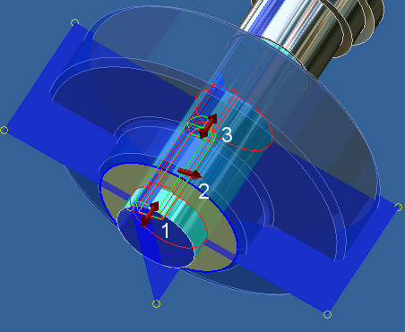
A.) Groove with rounded ends

1. Use grip to specify placement from the start edge.
2. Use the grip to specify the rotation position.
|
A graphic preview of the selected geometry and groove type are displayed in Autodesk Inventor. You can use grips to specify groove length, for example. |
|
|
Preview and available grips are different for three possible types of groove: |
|
|
A.) Groove with rounded ends |
|
|
|
|
|
1. Use grip to specify placement from the start edge. |
|
|
2. Use the grip to specify the rotation position. |
|
|
3. Use the grip to specify the key length. Groove length is automatically updated according to the key length. |
|
|
B.) Groove with one rounded end |
|
 |
|
|
1. Use the grip to specify placement from the start edge. |
|
|
2. Use the grip to specify the rotation position. |
|
|
3. Use the grip to specify the key length. Groove length is automatically updated according to the key length. |
|
|
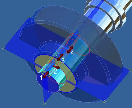
C.) Plain groove |
|
 |
|
|
1. Use the grip to specify placement from the start edge. |
|
|
2. Use the grip to specify the rotation position. |
|
|
3. Use the grip to specify the key length. Groove length is automatically updated according to the key length. |
|
|
4. Use the grip to specify the groove length. |