General Dimensions
You can create general dimensions in orthographic or isometric views. The geometry you select determines the dimension type and the options available in the context menu.
You can override the dimension text, which does not affect the model geometry.
You can change the dimension precision and tolerance, edit the leader and arrowheads, or modify the content of dimension text.

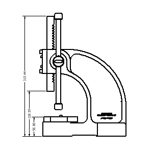
Baseline Dimensions and Baseline Dimension Sets
Creates multiple dimensions that display the orthogonal distance between the origin (base line) and selected edges or points. The first edge or point selected is the origin geometry. You can create individual dimensions or a dimension set.
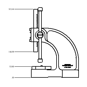
Ordinate Dimensions and Ordinate Dimension Set
Creates multiple ordinate dimensions in a single process. Ordinate dimensions automatically align as you place them. If dimension text overlaps, you can modify the dimension position or dimension style. You can create individual dimensions or a dimension set.
Retrieve Dimensions
Displays all model dimensions, or only dimensions related to selected parts or features. You select the dimensions to maintain in the drawing view.
Only model dimensions parallel to the view plane are available.
Model dimensions can be modified to manipulate the part file.
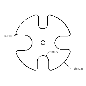
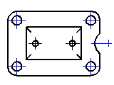
Center Marks
Center marks are added to the selected arc or circle. Center mark extension lines are automatically sized to fit the geometry.
Center marks can be added individually or using the automated centerlines command.
Centerlines
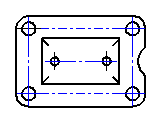
Creates centerlines for selected edges, at the midpoint for lines, or at the center point of arcs or circles. Creates a circular centerline when features form a circular pattern.
Autodesk Inventor supports three types of centerlines: bisector, centered pattern, and axial.
Hole/Thread Notes
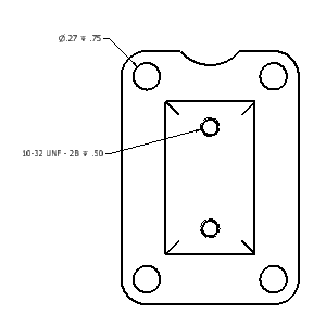
Hole or thread notes display the information from hole, thread, and cylindrical cut extrusion features on a model. The style of the hole note varies depending on the type of feature selected.
Chamfer Notes
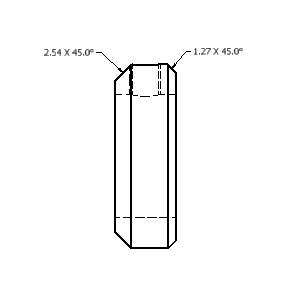
Chamfer notes contain distance and angle measurements for selected model edges or sketched lines.
You can attach chamfer notes to angled edges in views and sketches. A chamfer edge and reference edge from different bodies, models, or sketches, must be part of the same view.
Symbols
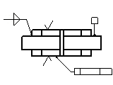
Various types of symbols are available: surface texture, welding, feature control frame, feature identifier, datum target, and datum identifier symbols. Symbols are created with or without a leader.
Sketch symbols are defined in the Drawing Resources and are placed like standard symbols. They are used to define custom symbols that are not available in Autodesk Inventor.
Bend Notes
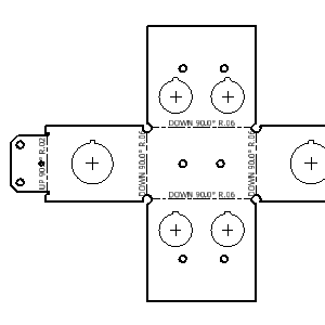
A bend not adds fabricating information to sheet metal bend, contour roll, and cosmetic centerlines. Bend notes can be added to flat pattern views of sheet metal parts.
A bend note is associated with the selected bend centerline. The default placement of the bend note is above the selected bend centerline. It constrains the bend text to the midpoint of the centerline and offsets by the Origin Offset value from the Dimension Style.
Punch Notes
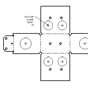
A punch note includes data related to the punch feature: for example the punch ID, angle, direction, depth, quantity note, and so on.
Punch notes can be added to flat pattern views of sheet metal parts.
Caterpillars
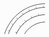
Weld caterpillars are used to denote weld features in 2D views. You can add weld caterpillars manually using the Caterpillar command. Add them automatically from weld features using Get Model Annotations > Get Weld Annotations on the context menu.
End Fills
End fills are used to represent the filled region indicating the end of a weld bead. You can add them manually using the End Fill command or automatically from weldment models using Get Model Annotations > Get Weld Annotations.
Change end fill appearance through object properties.

Balloons
Balloons are annotation tags that identify items listed in a parts list. Balloons can be placed individually or automatically for all components in a drawing view. You can add balloons to a custom part after it is added to the parts list.
The balloon shape and value can be overridden using Edit Balloon on the context menu. You can combine balloons to use a single leader using the attach balloon options on the context menu.

Parts lists
Parts lists display data saved in the assembly bill of materials. The parts list can be modified to include different columns or overridden values. The bill of material data can be modified from the drawing file or the assembly file.
Custom parts can be added to the parts list to include items that are not modeled such as paint or grease.

Tables
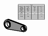
You can create a general, configuration, or bend table.
You can create a general or configuration table.
A general table can have a default number of rows and columns, or you can customize its size. The general table can reference external data from .xls, .xlsx, or .csv files, or you can enter any other type of data you need.
In drawings of iParts and iAssemblies, configuration table rows represent the members of the factory. You can specify the columns to include in the configuration table, such as exclusion status and values that are different among members.
A bend table is created if a sheet metal part is the source of the table. Bend tables contain bend information such as angle and radius.
Hole Tables
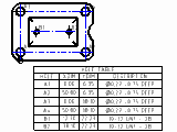
Hole tables show the size and location of the hole features in a model. When a hole table is added, each individual hole receives a hole tag and a corresponding row is added to the table.
You can also add center marks, punch features, and cylindrical cut extrusion to a hole table by editing the table.
Revision Tables and Tags
Revision tables include information about design changes. Revision tables can be created for the entire drawing file or a single sheet.
A revision tag marks an object changed by design revisions. The default revision level for the tag is the latest revision in the table. The revision level of the tag can be changed using the context menu.

Text or Leader Text
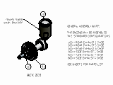
Use Text to add general notes to a drawing. General notes are not attached to any view, symbol, or other object in the drawing.
Use Leader Text to add notes to objects in a drawing. If you attach the leader line to geometry in a view, the note is moved or deleted when the view is moved or deleted.
