You can define multiple User Coordinate Systems (UCS) in Autodesk Inventor.
You can select a UCS when you export data using Author Building Components. It ensures that the model is imported in the appropriate orientation in the receiving application.
Position UCS relatively to the Origin
In a part file you can place UCS relatively to the Origin.
- Open a part or assembly file.
- Open a part file.
- On the ribbon, click 3D Model tab
 Work Features panel UCS
  .
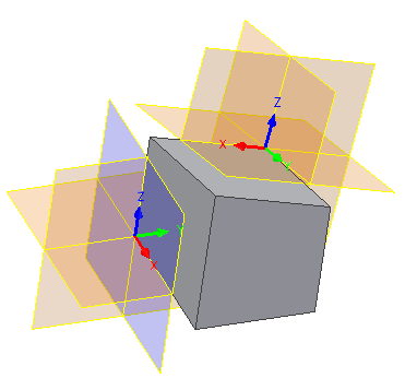
. - Click anywhere in the graphics window to specify the origin of UCS. Or, specify the UCS origin using HUD. To change the position of the UCS origin, right-click and select Restart.
- Click the axes to move the UCS in the desired direction. Click the arrowheads to rotate the UCS.
- Right-click, and select Finish. UCS is placed to the specified location. UCS defines six parameters for its positional and rotational placement values.
Position UCS relatively to existing geometry
In a part file, UCS can be positioned relatively to existing geometry.
When you define UCS, you can enter the values in HUD (Heads Up Display).
- Open a part file with an inserted component.
- On the ribbon, click 3D Model tab Work Features panel UCS .
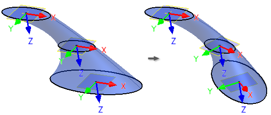
- Specify an origin point. This is the point (0, 0, 0) on the new UCS. When placing UCS using existing geometry, you must always select three points (the origin and direction of X and Y axes). When you make an appropriate selection, the particular graphical representation of UCS turns black.
- Specify a point to select the direction of X axis.
- Specify a point to select the direction of Y axis. Now, the UCS is defined and placed. UCS defines six parameters - three positional coordinates, and three coordinates to drive the rotation angles.The coordinates and rotations are relative to the target geometry, so after the initial placement, the parameter values are set to 0. If you redefine the UCS to offset its position, the parameters reflect the relative transformation.
Align sketch geometry with UCS
You can select the UCS triad as an input for 2D Sketch command. You can also use the UCS work features for 2D Sketch.
The origin of the sketch is aligned with the UCS center point, and the center point is projected to the sketch.
If the UCS position changes (either because its parameters or target geometry changed, or because the UCS was redefined), the sketch is updated.