Standard Calculation Procedure
1. Common solution for combined loading

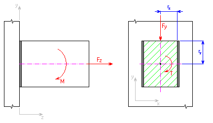
Loading in the plane perpendicular to the weld plane induces a tensile or pressure stress σ in the weld.
Normal stress caused by axial force F Z
![]()
where:
|
F Z |
axial force [N, lb]. |
|
|
A |
throat area of the weld group [mm 2 , in 2 ]. |
Normal stress caused by bending moment M
![]()
where:
|
u |
constant |
|
|
- for calculation in metric units u = 1000 |
||
|
- for calculation in English units u = 12 |
||
|
M |
bending moment [Nm, lb ft] |
|
|
r Y |
distance of investigated weld point from the weld group center of gravity in the y-axis direction [mm, in] |
|
|
I |
moment of inertia of weld group to the neutral x-axis [mm 4 , in 4 ] |
Total normal stress
σ = σ F ± σ M [MPa, psi]
where:
|
σ F |
normal stress caused by the axial force F Z [N, lb] |
|
|
σ M |
normal stress caused by the bending moment M [mm, in] |
Loading in the weld plane induces a shear stress τ in the weld:
Shear stress caused by shearing force F Y
![]()
where:
|
F Y |
shearing force [N, lb] |
|
|
A |
throat area of the weld group [mm 2 , in 2 ] |
Shear stress caused by torsion moment T
- x-component of stress
![]()
- y-component of stress
![]()
where:
|
u |
constant |
|
|
- for calculation in metric units u = 1000 |
||
|
- for calculation in English units u = 12 |
||
|
T |
torque [Nm, lb ft] |
|
|
r X |
distance of investigated weld point to the weld group center of gravity in the y-axis direction [mm, in] |
|
|
r Y |
distance of investigated weld point to the weld group center of gravity in the y-axis direction [mm, in] |
|
|
J |
polar moment of inertia of weld group [mm 4 , in 4 ] |
Total shear stress
for circular weld:

for other welds:
![]()
where:
|
τ XT |
x-component of shear stress caused by torque T [MPa, psi] |
|
|
τ Y |
shear stress caused by shearing force F Y ' [MPa, psi] |
|
|
τ YT |
y-component of shear stress caused by torque T [MPa, psi] |
Resultant shear stress in the investigated point of weld
![]()
where:
| σ |
total normal stress [MPa, psi] |
|
| τ |
total shear stress [MPa, psi] |
2. Loading with bending force F Y

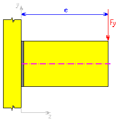
For calculation purposes, the bending force can be substituted by the combination of shearing force F Y acting in the weld plane and the bending moment M acting in the plane perpendicular to the weld plane. Then the stress in the weld can be calculated using the previously mentioned procedure.
The bending moment is defined by a formula:
![]()
where:
|
F Y |
shearing force [N, lb] |
|
|
e |
arm of bending force [mm, in] |
|
|
u |
constant |
|
|
- for calculation in metric units u = 1000 |
||
|
- for calculation in English units u = 12 |
3. Loading with common force F Y

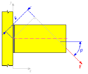
For calculation purposes, the common force F can be substituted by the combination of shearing force F Y acting in the weld plane with the axial force F Z and the bending moment M acting in the plane perpendicular to the weld plane. Then the stress in the weld for so defined loading can be calculated using the above mentioned procedure.
The particular components of the loading are defined by formulas:
- bending moment
![]()
- axial force
F Z = F cos ϕ [N, lb]
- shearing force
F Y = F cos ϕ [N, lb]
where:
|
F |
acting force [N, lb] |
|
|
r F |
force arm related to the weld group center of gravity [mm, in] |
|
|
u |
constant |
|
|
- for calculation in metric units u = 1000 |
||
|
- for calculation in English units u = 12 |
||
| ϕ |
direction angle of acting force [°] |
Method of Comparative Stresses
1. Common solution for combined loading
Compared with the standard calculation method, the method of comparative stresses approaches a different way to calculate stresses caused by the axial force or bending moment that actuate in the plane perpendicular to the weld plane. Generally the stress in fillet welds has normal and tangential components. The method of comparative stresses is based on the fact that the shear strength of weld metal is lower than the tensile strength. To simplify the calculation, weld joints are only checked for shear stresses. But the calculation method is the same as in the standard calculation method. Used calculation formulas are also similar.
Loading in the perpendicular plane to the weld plane:
Shear stress caused by axial force F Z
![]()
where:
|
F Z |
axial force [N, lb]. |
|
|
A |
throat area of the weld group [mm 2 , in 2 ]. |
Shear stress caused by bending moment M
![]()
where:
|
M |
bending moment [Nm, lb ft] |
|
|
r Y |
distance of investigated weld point from the weld group center of gravity in the y-axis direction [mm, in] |
|
|
u |
constant |
|
|
- for calculation in metric units u = 1000 |
||
|
- for calculation in English units u = 12 |
||
|
I |
moment of inertia of weld group to the neutral x-axis [mm 4 , in 4 ] |
Loading in the weld plane:
Shear stress caused by shearing force F Y
![]()
where:
|
F Y |
shearing force [N, lb] |
|
|
A |
throat area of the weld group [mm 2 , in 2 ] |
Shear stress caused by torque T
- stress x-component
![]()
- stress y-component
![]()
where:
|
T |
torque [Nm, lb ft] |
|
|
u |
constant |
|
|
- for calculation in metric units u = 1000 |
||
|
- for calculation in English units u = 12 |
||
|
r Y |
distance of investigated weld point to the weld group center of gravity in the y-axis direction [mm, in] |
|
|
r X |
distance of investigated weld point to the weld group center of gravity in the x-axis direction [mm, in] |
|
|
J |
polar moment of inertia of weld group [mm 4 , in 4 ] |
Total shear stress in the investigated point of weld
![]()
where:
|
τ XT |
x-component of shear stress caused by torque T [MPa, psi] |
|
|
τ Y |
shear stress caused by shearing force F Y ' [MPa, psi] |
|
|
τ YT |
y-component of shear stress caused by torque T [MPa, psi] |
|
|
τ Z |
shear stress caused by shearing force F Z [MPa, psi] |
|
|
τ ZM |
shear stress caused by bending moment M [MPa, psi] |
2. Calculation of comparative stress σ s
The comparative stress is determined from calculated partial stresses according to the formula.

while for the x-component of stress that actuates in the investigated point of weld, perpendicularly to the weld direction, the α X = α 3 formula is applied. In the opposite case α X = α 4 . The same applies for the y-component of the stress actuating perpendicularly to the weld direction, that is α Y = α 3 or α Y = α 4 .
|
τ XT |
shear stress x-component caused by torque T [MPa, psi] |
|
|
τ Y |
shear stress caused by shearing force F Y [MPa, psi] |
|
|
τ YT |
shear stress y-component caused by torque T [MPa, psi] |
|
|
τ Z |
shear stress caused by shearing force F Z [MPa, psi] |
|
|
τ ZM |
shear stress caused by bending moment M [MPa, psi] |
|
|
α 3 |
conversion factor of weld joint for fillet end weld [-] |
|
|
α 4 |
conversion factor of weld joint for fillet end weld [-] |