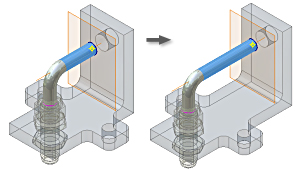
Usually, 3D sweep features are used in an assembly context for routed parts, cabling, and wiring. Their position is relative to already placed components .
Use these tips to help create 3D sweep features:
- Usually, in an assembly, create a separate part file for a 3D sweep feature.
- Determine the geometry on existing parts you must insert into the 3D sketch for the sweep path. Use Include Geometry to project it into the 3D sketch.
- Use adaptive work features (using geometry on other parts for reference) to position points for 3D lines used in the 3D sweep feature.
- Use
adaptive work features
to position points for 3D lines used in the 3D sweep feature.
When creating a 3D line, select a vertex on an existing part to create an adaptive work point automatically.
When creating a 3D line, select a vertex on the part to create an adaptive work point automatically.
- On the ribbon, click Tools tab
 Options panel
  Application Options
  Part tab and then select the Auto-Hide option to simplify the 3D sketch display. In-line work features are hidden as soon as they are consumed by a feature.
 - Create in-line work features where possible. For example, create a work point at the intersection of work planes.
- Create profile sketches on work planes that are perpendicular to the start point of the 3D line.
- Create 2D profile geometry after you create 3D sketch geometry. If you create it before the 3D sketch, drag the 2D sketch in the browser to a position below the 3D sketch.
- Keep in mind the 3D sweep feature when you modify existing parts. If you delete a part or edit geometry on which the 3D sketch depends, use Redefine Point to reattach the 3D sketch lines to valid points or vertices.
- Keep in mind the 3D sweep feature when you modify existing parts. If you edit geometry on which the 3D sketch depends, use Redefine Point to reattach the 3D sketch lines to valid points or vertices.