The Generate Core and Cavity command creates the required files for the core and cavity.
Generate a core and cavity
- Generate the patching surface, runoff surface, and workpiece.
- In the
Core/Cavity tab,
Parting Design panel, click
 Generate Core and Cavity.
- Set the Repair Tolerance value to resolve small gaps.
- Optionally, in the
Preview tab of the dialog box, click
Preview/Diagnose.
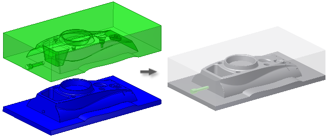
Use the Opacity Settings slider controls to set the transparency value of the bodies.
Use the Body Preview slider control to preview the physical separation between the bodies.
- Optionally, if you clicked
Preview/Diagnose, the parting surface is analyzed and the Parting Diagnostics
tab is available. Click to view a list of any problems detected.
Note: Problems with the parting surface are listed in the Problems list. Click an item in the list to highlight the corresponding element in the graphics window. Right-click an item in the list, and then click Find in Window to highlight and zoom to the corresponding element in the graphics window.
- Click OK to start the file creation.
- Optionally, if Prompt for File Names is enabled, you can set the file names and locations in the File Naming dialog box.
- Click OK to create the core and cavity. Corresponding nodes display in the Mold Design browser.
Parting Diagnostics
To evaluate the parting surfaces, in the Generate Core and Cavity dialog box, click Preview/Diagnose. Click the Parting Diagnostics tab to verify they can be used to generate the core and cavity successfully. If the parting surface has undercuts or is leaky due to a hole or breach, the dialog box, Problems list section, lists the problems.
- In the Core/Cavity tab, Parting Design panel, click Generate Core and Cavity.
- In the Generate Core and Cavity dialog box, click Preview/Diagnose.
- On the Parting Diagnostics tab, view the Problems list.
- Optionally, select a problem in the list to highlight in the graphics window.
Edit a core cavity
- In the Mold Design browser, right-click the Core Cavity node.
- Select Edit Feature in the context menu.
- In the Generate Core Cavity dialog box, set the Repair Tolerance. Use Preview/Diagnose to analyze the model for errors.
- Click OK when finished.
Note: You can generate a sick core cavity and use normal Inventor modeling commands to repair significant errors. When finished, return to the Mold Design browser and use Edit Feature to generate a successful core cavity.
Delete a core cavity
- In the Mold Design browser under Core Cavity, right-click the Core or Cavity node, and then click Delete.