Provides access to the appearance assets in the current document and in the accessible libraries, as defined in the project file.
Access
Quick Access Toolbar: 
Tools tab  Materials and Appearances panel Adjust .
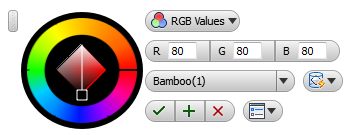
Appearance Mini-Toolbar
 Grip
Grip -
Click-drag to reposition the mini-toolbar
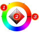 Color Wheel
 -
The Color Wheel consists of 1) a hue wheel, 2) a diamond, and 3) a slider (thin black bar).
Drag the slider to select a color, select a hue within the diamond. The diamond defines saturation from 0% (left) to 100% (right) and brightness from white (top) to black (bottom).
For most appearance types, other than metal, liquid, and stone, the selected object color displays in the color wheel. For metal, liquid, and stone, the Tint value is displayed.
 Color Picker Cursor
 -
Color Picker Cursor sits within the diamond. Click-drag the cursor to the hue you want to use.
 Current|Previous Color
 -
Current|Previous Color displays the previous color so you can easily switch between two colors. Color wheel updates with selected color information.
- Color Mode
-
Color Mode select the RGB (default) or HSB mode for use in specifying the color.
 RGB: Red, Blue, Green
  HSB: Hue, Saturation, Brightness
 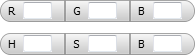 Color values
 -
Color values specify the desired values for the color mode and selection.
RGB values are expressed in a range from 0 through 255, increasing from no color (0) to full color (255).
HSB values are expressed as percentages.
 Save Appearance
 -
Save Appearance saves modifications made to the current appearance. Enabled only when modifications have been made to an appearance.
 Appearances
 -
Appearances Click the down-arrow to display of the list of available appearance textures.
 Texture Mapping
 -
Texture Mapping specifies the texture image mapping type.
Component level
- Automatic Maps image onto objects using model topology.
- Box Maps image onto box-like objects. The texture is repeated on each side.
- Cylindrical Maps image onto a cylindrical object; horizontal edges are wrapped together but not the top and bottom edges. The image height is scaled along the cylinder axis.
- Planar Maps the image onto the object as a projection. The image is not distorted on faces normal to the projection, but is distorted on nonnormal faces. The image is not scaled to the object. This mapping is commonly used for 2D planar faces.
- Spherical Maps image onto a spherical object. The top edge of the map is compressed to a point at the “north and south poles” of the sphere.
Face level
- Automatic Default
- Align Direction Analyzes object, and realigns the texture direction.
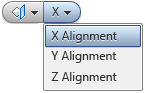 Texture alignment
 -
When Planar mapping is selected, texture alignment options are enabled.
- X Alignment
- Y Alignment
- Z Alignment
-

-
OK | Apply | Cancel
 Options
 -
Options Specifies the in-canvas mini-toolbar behavior.
- Pin Mini-Toolbar Position
- Auto Fade