New iLogic Components and Management Behavior
Multiple new iLogic assembly functions make it easier for you to write rule code to add, modify, and delete components and constraints. Here are some examples:
- Components.Add: Ensures the component exists and that it has specified properties.
- Components.AddiPart: Creates/updates an occurrence using an iPart factory and specification of a member.
- ThisAssembly.BeginManage and ThisAssembly.EndManage: Allow you to delete components without specifically calling Components.Delete.
In the following example, OptionA is a True/False parameter in the assembly. If the parameter is set to True, the component named Occ A will be added or updated. If it is False, the component won't be added or it will be deleted. iLogic ensures that Occ A is present if-and-only-if OptionA is True.

When the EndManage code runs: If OptionA is false and if the component named Occ A already exists in the assembly, it will be automatically deleted.
The principle is: Every time a BeginManage/EndManage block runs, you must call a function to add only the components you want included in that block.
For more information on the functions supported in iLogic, see iLogic API Reference.
New Document Units Geometry
There are new functions which use document-units instead of database-units for the coordinate values and objects representing Points, Vectors, and Matrices. These objects can be used to specify the location and orientation of components created by Components.Add and related functions. Use ThisDoc.Geometry.Point() or similar functions to create the objects.
New iLogic Assembly Add Constraints Functions
The new iLogic Relationships (Add) functions allow you to create an iLogic assembly whose occurrences and constraints are generated by a rule. The rule will re-generate or update the content if any of the relevant parameters values are changed.
See below for the list of the new functions:
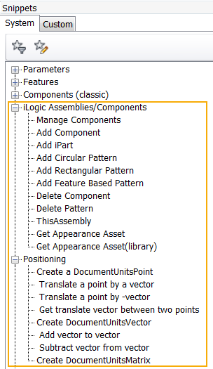
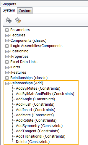
For more information, see iLogic API Reference
New Capture Current State Commands
The Capture Current State command is enhanced to support the following:
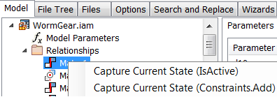
- Capture Current State (Components.Add) Captures the state of the selected components using Components.Add. Ignores related constraints.
- Capture Current State (Components Constraints.Add) Captures the state of the selected components and related constraints using Components.Add.
- Capture Current State (Constraints.Add) Captures the state of the selected constraints using Constraints.Add. Only available if the file contains a constraint.
- Capture Current State (Patterns.Add) Captures the state of the selected pattern. Available if the file contains an assembly pattern.
| The new Capture Current State commands are available by right-clicking on one or more files in the Rules Editor on the Model tab. | Here's an example of a rule generated from the Constraints.Add command. Once added to the rule editor, you can make any modifications you want to the content directly in the rule editor. |
|

|
Multi-select components in the Model tree in the Rule Editor to capture the state of multiple components all at once. If you are capturing constraints between components, this ensures these are only captured once.
For more information, see To Work with Rules in iLogic
Use Assign Name to Identify Geometry for Constraints
You can now assign names to faces and edges, and then create a rule that adds the constraint(s) directly to the face or edge with the assigned name.
Assign a descriptive name to the constrained geometry to make it easier to identify the geometry in the rule editor.
To begin, assign a name to a face or edge:
|
Step 1 In a part file, right-click on the geometry that is or will be constrained to another part, and select Assign Name. |
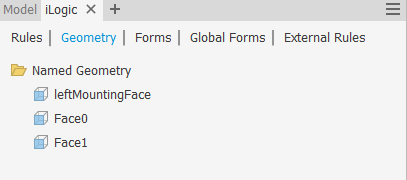
The assigned name displays in a new Geometry tab in the iLogic browser and on the geometry in the graphics window (part file only).
Tip: Turn on and off the display of the assigned name in the graphics window using the context menu option Show/Hide Label.
|

|
|
Next, create a rule that will add the constraint(s) directly to faces and edges with the assigned names:
|
Step 2 In the assembly file, in the Edit Rule dialog box on the Model tab, multi-select the part names, right-click, and then select Capture.Current.State (Components Constraints.Add) from the context menu. |
The rule editor populates with the new rule. The constraint will be re-created whenever you run the rule.
Note: If the geometry was not assigned a name in the part file, the Rule Editor creates a generic name for the geometry.
|

|

|
For more information, see To Work with Rules in iLogic.
Enhancement to the iLogic Help for Functions
Help for iLogic functions and arguments are now available from the iLogic API Reference help node. This help content is in english only.
For more information on the functions supported in iLogic, see iLogic API Reference.
