Synopsis
This design describes a three-dimensional wire frame line. The line design has numerous group rules allowing it to be defined using points, direction, length, and tangency to other parts.
Mixins
LineMixin
CurveMixin
InkStrokedMixin
Canonicals
| Name | Type | Description |
|---|---|---|
| p0 | point | Start point of the line |
| v0 | vector | Direction vector of the line |
| u0 | number | Curve parameter at the start of the line. By default, its value is 0.0. |
| u1 | number | Curve parameter at the line end point. By default, this is the length of the line. |
| defaultEnd | number | Default end parameter of the line. This is usually the length of the line. |
Parameters
| Name | Type | Description |
|---|---|---|
| alignment | integer | Aligns the line to one of the reference axes. 1 is alignment along the X axis, 2 is for the Y axis, and 3 is for the Z axis, respectively. |
| angle | number | The angle in degrees from the reference x axis. Used to orient the line. |
| baseAxis | part | This is the part used as a reference for specifying the angle. The baseAxis.localFrame z axis is used to measure the angle: input. |
| dirVector | vector | Direction of the line from the start to end point . |
| distance | number | Distance from the origin of the offsetFrom part. |
| end_ | number | Parameter at the end of the line. |
| length | number | Length of the line. |
| offsetFrom | part | A line from which to offset this line. |
| onRight1 | boolean | If the line is constrained by being tangent to two arcs, this parameter is used to determine the location of the line. An imaginary line is constructed from the center of tanArc1 to the center of tanArc2. This parameter should be true if the new line is to the right side of the imaginary line at the tanArc1 start, otherwise it should be false. |
| onRight2 | boolean | If the line is constrained by being tangent to two arcs, this parameter is used to determine the location of the line. An imaginary line is constructed from the center of tanArc1: to the center of tanArc2. This parameter should be true if the new line is to the right side of the imaginary line at the tanArc2: end, otherwise it should be false. |
| parallelTo | part | A line that this line should copy its orientation from. |
| perpendicularTo | part | A line that this line should use to orient itself perpendicular to. |
| start | number | Curve parameter at the start of the line. Changing this number from the default of 0 will change the start point of the line. |
| tanArc2 | part | The arc part that this line should be tangent to at end:. The parameter onRight2 has to be used to fully constrain the line. |
| tanArc1 | part | The arc part that this line should be tangent to at start:. The parameter onRight1 has to be used to fully constrain the line. |
| thruPoint1 | point | The first point that the line should pass through. This point does not have to coincide with the start point of the line if the curve parameter start: has been modified. |
| thruPoint2 | point | The second point that the line should pass through. This point does not have to coincide with the end point if the curve parameter end: has been modified. |
Rules
| Name | Type | Description |
|---|---|---|
| endPoint | point | Point at the line's end. Calculated from p0:+(u1:*v0:). |
| polygonPoints | list | A list of two points , the startPoint: and endPoint:, calculated from {startPoint:, endPoint:}. |
| startPoint | point | Point at the line's start. Calculated from p0:+(u0:*v0:). |
| midPoint | point | Midpoint of the line. |
Methods
curveParamNearPoint( p as Point ) As NumberReturns the curve parameter nearest the input point .
pointForParam( param As Number ) As PointReturns the point on the line with the given input parameter.
Group Rules
<length> Sets the curve parameters u0: and u1: to be 0.0 and length: respectively.
<end_ length> Sets the start and end curve parameters given the end curve parameter and the length.
<start length> Sets the start and end curve parameters given the start curve parameter and the length.
<end_> Sets the end parameter of the line.
<start> Sets the start parameter of the line.
<onRight1 onRight2 tanArc1 tanArc2> Specifies a line between two arcs that it is tangent to. The onRight1 and onRight2 parameters are used to determine in which of the four possible positions to orient the line. An imaginary line is created between the center of tanArc1 and tanArc2. OnRight1 tells if the line starts at the tangent point on the arc that is to the right of this imaginary line. Similarly, onRight2 tells if the line ends at the tangent point on the arc that is to the right of this imaginary line.
<onRight1 tanArc1 thruPoint1> Specifies a line passing through one point and tangent to an arc.
<angle baseAxis thruPoint1> Specifies a line through a point at an angle to baseAxis. The entity used for baseAxis must handle the line protocol.
<angle thruPoint1> Specifies a line through a point at an angle to the X axis of the localFrame.
<alignment thruPoint1> Specifies a line aligned with an orthogonal axis of the localFrame. The value for alignment is a coded integer, where 1 indicates the X axis, 2 indicates the Y axis, and 3 indicates the Z axis.
<offsetFrom distance onRight1> Specifies a line offsetFrom another line at a given distance.
<parallelTo thruPoint1> Specifies a line through a point and parallel to another entity. The parallelTo part must handle the line protocol.
<dirVector thruPoint1> Specifies a line through a point and aligned with a vector.
<thruPoint1 thruPoint2> Specifies a line through two points.
<thruPoint1 perpendicularTo> Specifies a line through a point and perpendicular to another entity. The perpendicularTo part must handle the line or arc protocols.
Meta Rules
<tanArc1 tanArc2> Determines the onRight1 and onRight2 parameters from the location of the mouse pick.
<tanArc1 thruPoint1> Determines the onRight1 parameter from the location of the mouse pick.
<offsetFrom distance> Determines the onRight1 parameter from the location of the mouse pick.
Example 1
| Name : | line_Ex01 |
| Design : | acDrawingDocument |
| Child Name : | Line_1 | |
| Child Design : | :Line | |
| Nam e | Type | Supplied |
| thruPoint1 | point | point(0, 0, 0) |
| thruPoint2 | point | point(3, 1, 0) |
Example 2
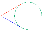
| Name : | line_Ex02 |
| Design : | acDrawingDocument |
| Child Name : | Line_1 | |
| Child Design : | :Line | |
| Name | Type | Supplied |
| thruPoint1 | point | point(0, 0, 0) |
| tanArc1 | part | Arc_1 |
| onRight1 | boolean | True |
| color | string | "blue" |
| Child Name : | Line_2 | |
| Child Design : | :Line | |
| Name | Type | Supplied |
| thruPoint1 | point | Line_1.startPoint |
| tanArc1 | part | Arc_1 |
| onRight1 | boolean | False |
| color | string | "orange" |
| Child Name : | Arc_1 | |
| Child Design : | :Arc | |
| Name | Type | Supplied |
| radius | number | 1 |
| endAngle | number | 270 |
| center | point | point(2, 0, 0) |
| color | string | "jungle green" |
Example 3
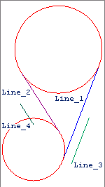
| Name : | line_Ex03 |
| Design : | acDrawingDocument |
| Child Name : | ArcBottom | |
| Child Design : | :Arc | |
| Name | Type | Supplied |
| radius | number | 1.25 |
| center | point | point(0, 0, 0) |
| color | string | "red" |
| Child Name : | ArcTop | |
| Child Design : | :Arc | |
| Name | Type | Supplied |
| radius | number | 1.75 |
| center | point | point(1, 4, 0) |
| color | string | "red" |
| Child Name : | Line_1 | |
| Child Design : | :Line | |
| Name | Type | Supplied |
| TanArc1 | part | ArcBottom |
| onRight1 | boolean | True |
| TanArc2 | part | ArcTop |
| onRight2 | boolean | True |
| color | string | "blue" |
| Child Name : | Line_2 | |
| Child Design : | :Line | |
| Name | Type | Supplied |
| TanArc1 | part | ArcBottom |
| onRight1 | boolean | True |
| TanArc2 | part | ArcTop |
| onRight2 | boolean | False |
| color | integer | "red violet" |
| Child Name : | Line_3 | |
| Child Design : | :Line | |
| Name | Type | Supplied |
| OffsetFrom | part | Line_1 |
| distance | number | 0.375 |
| length | number | 2 |
| onRight1 | boolean | True |
| color | string | "jungle green" |
| Child Name : | Line_4 | |
| Child Design : | :Line | |
| Name | Type | Supplied |
| parallelTo | part | Line_2: |
| thruPoint1 | point | point(0, 1, 0) |
| color | string | "teal" |
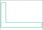
Example 4
| Name : | line_Ex04 | |
| Design : | acDrawingDocument | |
| Name | Type | Formula |
| a | number | 1.25 |
| b | number | 0.75 |
| t | number | 0.15 |
| ptList | list |
{point(0,0,0), point(a,0,0), point(a,t,0), point(t,t,0), point(t,b,0), point(0,b,0)} |
| Child Name : | curves | |
| Child Design : | :Line | |
 Child List
?
Child List
? |
||
| Name | Type | Supplied |
| thruPoint1 | point | nth(child.index, ptList) |
| thruPoint2 | point | nth(child.index, rest(ptList)+{first(ptList)}) |
| color | string | "jungle green" |
| Quantity | integer | length(ptList) |