This section shows how to use Visual Studio to create a simple Windows Forms user interface that runs inside of an Inventor AddIn. We assume that you have experience with creating Inventor Add-ins, and so we focus on using the UI Tools controls. The actual Inventor add-in contains a Show UI button that displays a form containing the various UI Tools controls.
Add References to UI Tools
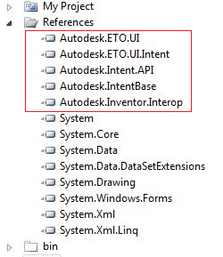
Before you can add any of the UI Tools controls to our add-in form, first add references to the UI Tools assemblies to the Visual Studio project. There are two DLL references that are required to use the UI Tools: Autodesk.ETO.UI.dll, and Autodesk.ETO.UI.Intent.dll. Also required are references to the core Intent Autodesk.Intent.API.dll and Autodesk.IntentBase.dll assemblies. Finally, because this UI runs as an Inventor add-in, we need a reference to Autodesk.Inventor.Interop.dll.
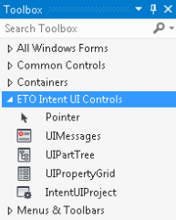
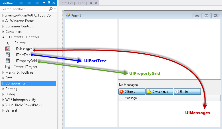
Once these DLL references are added, add the various UI Tools controls from the Visual Studio Toolbox. These controls are in the Toolbox on a tab named ETO Intent UI Controls.
IntentUIProject
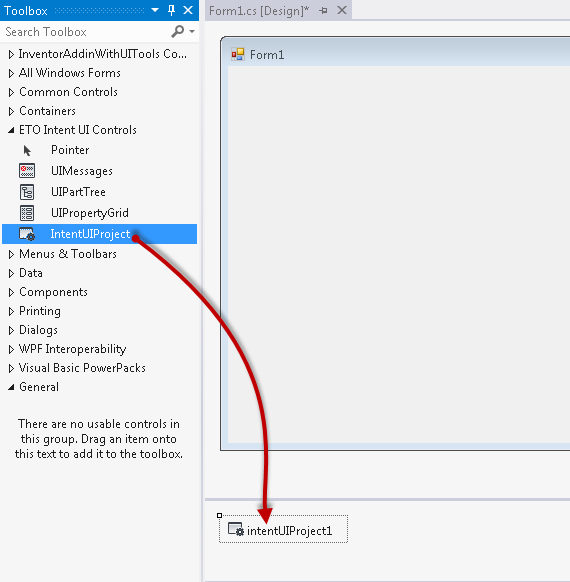
The IntentUIProject control serves as the controller for the UI Tools. It houses all of the project level information, and manages all of the UIParts. To ensure that the other UI Tools controls function, drag an IntentUIProject from the toolbox onto our form to add it to the UI.
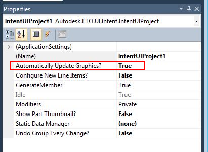
By default, the IntentUIProject does not cause graphics to update automatically when a change to the Intent model takes place. This behavior is to allow you to make a series of changes without waiting for time consuming graphics updates between each one. However, our sample project is simple enough that enabling automatic updates does not pose a significant performance cost. Go to the IntentUIProject that we added to our form and in the Properties, switch Automatically Update Graphics? to True.
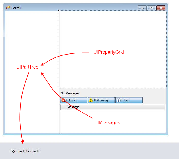
UIPartTree, UIPropertyGrid, and UIMessages
Before you add the remaining three controls to the UI, add a few SplitterPanels. Then you can easily position and resize them within the form. Our UIPartTree is on the left, and the UIPropertyGrid and UIMessages stack vertically on the right.
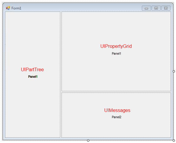
Now, drag the corresponding controls to their locations within the SplitterPanels, and then set their Dock properties to Fill.
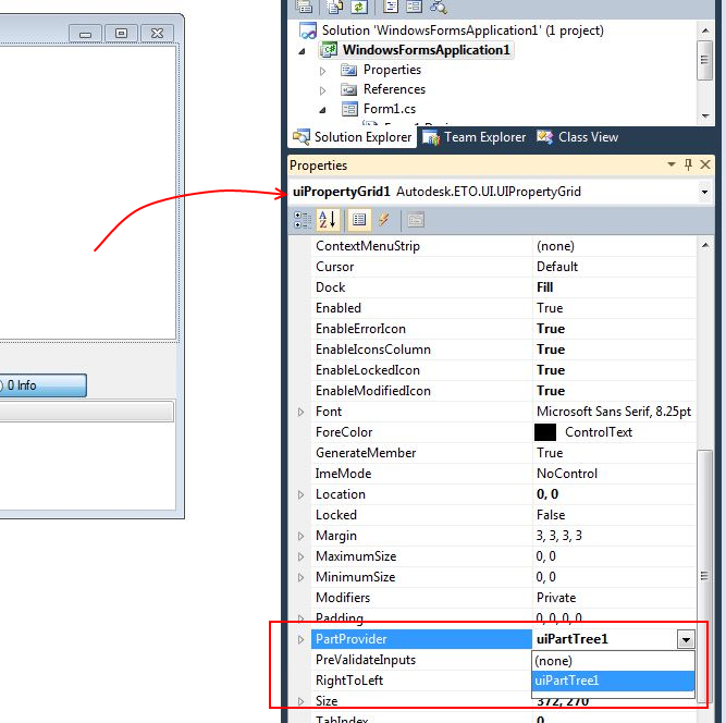
Now the controls are on the form where we want them. Next, wire them up to the IntentUIProject component we added originally. The simplest method is to set their PartProvider properties from within the Visual Studio designer. Set the part provider for the UIMessages control and the UIPropertyGrid control to the UIPartTree control:
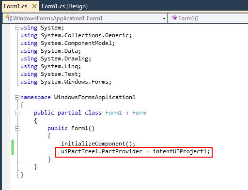
Set the part provider for the UIPartTree control to the UIProject control in code:
PartProviders
PartProviders are any components that implement the IPartProvider interface from the Autodesk.ETO.UI.dll. This interface tracks the currently selected UIPart within that component. For example, the UIPartTree implements IPartProvider, and its selected UIPart is whichever UIPart is selected in the tree. The IntentUIProject is also a PartProvider. However, its selected UIPart is always the Root part in the model. For this reason, the Root part in the Intent model must mix in UIPartMixin.
Many components accept PartProviders as parameters. They can keep up with information about the currently selected part within their referenced PartProvider. The UIPropertyGrid is an example of a control that accepts a PartProvider.You can set the UIPropertyGrid PartProvider property to the UIPartTree. Then whenever you select a new UIPart in the tree, the UIPropertyGrid automatically updates itself with the properties of the newly selected part.
Some controls implement IPartProvider, and also accept a PartProvider as a property. The UIPartTree is an example. Set the root node in the UIPartTree by setting its PartProvider property. In your case, you want the UIPartTree to be the entire model, so set its PartProvider property to the IntentUIProject that we added earlier. Then the root of the UIPartTree is the root UIPart of the model, since the selected UIPart of the IntentUIProject is always the root.
The following image shows the PartProvider relationships between the various controls in our UI.
The UIPropertyGrid and UIMessages both have their PartProvider properties set to the UIPartTree. The UIPartTree has its PartProvider set to the IntentUIProject.
Run Inventor UI Add-in
First you create the UI form for the Inventor add-in, and place and wire all of the UI Tools controls to the Intent model using their PartProviders. Then you can build the add-in, and run Inventor. Once you open the table assembly ("Table.iam"), you have an "Autodesk ETO UI" ribbon tab, that contains a single "Show UI" button. This button shows the form that we created, and the UI Tools controls are populated based on our Intent designs. The sample has a postbuild step to register the add-in and copy it to the correct locations. If you need troubleshooting, see the sample readme file for details.