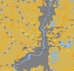
 Specify the appearance of polyline features.

Each line pattern consists of a symbol (for example, a dash, dot, or graphical symbol) and a space. For solid lines, the gap (repeat interval) is zero. Some line symbols can include text. For example, you can include highway symbols with route numbers when styling roads. You can specify the position and orientation of the symbols. You can use AutoCAD line styles for feature-based geometry. You can specify an offset relative to polyline start and end points. You can use expressions for values.
The Style tab appears on the ribbon whenever you select a feature layer in the Display Manager. The Style tab contains a subset of styling options that let you change common style properties. For defining line styles initially, use the Style Line dialog box.