One class or layer is designated the Source and one is designated the Overlay. The Overlay operation produces an output layer that is also saved as a separate SDF feature store. The contents and attributes of the new layer vary, depending on the type of Overlay operation you perform.
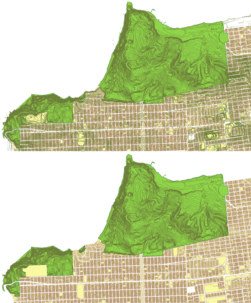
An overlay was used to display the contours only inside the green polygon.
You can overlay feature classes with up to a million features, depending on the size and complexity of the features.
Setting Tolerance Units
You can set a tolerance value for both Sliver Tolerance and Ordinate Tolerance. Sliver tolerance determines which polygons should be separate features and which are too small and should be part of neighboring features. Ordinate tolerance specifies how far apart two nodes need to be to be considered separate points in the output layer. For each of these tolerance settings, you first choose a unit and then set a value. The unit you set depends on the coordinate system you are using.
If you use a geographical coordinate system that specifies measurements in degrees, you must set Sliver Tolerance in ground units (for example, square feet or meters). By default, Sliver Tolerance is in square meters. These tolerances represent measurements taken locally, and are subject to errors that do not vary greatly by location. However, Ordinate Tolerance is not truly a distance unit, and should be expressed in degrees for geographical systems.
Attributes in the Resulting Layer
Use the Split and Merge Rules dialog box to set attributes for features that are split as a result of an overlay operation. If you do not set these rules, such features follow default rules. Merge rules do not apply. If you overlay two feature sources that you used previously in a different map, you must reset the rules for the new map.
In some cases, attributes from both the Source and Overlay are written to the output. If this results in attributes that have the same name, each one will have the original attribute name and a numeric suffix. For example, you can overlay two layers called Cities and Parcels. If both have a Name attribute, the resulting layer will have attributes called “Name_1” and “Name_2.”
Selecting Source and Overlay Geometries
The geometry in the feature classes or layers you select determines the other choices in the dialog box. You can combine only certain types of geometries. For example, Union and Symmetric Difference support polygon/polygon comparisons only. If you select point geometry for Source, you can select only polygon geometry for Overlay.
The order of the geometries you select is important. To compare line and polygon geometries, the line geometry must be the Source layer. If you select a polygon geometry as the Source, line geometries are not available as the Overlay.
The available choices for Type depend on the geometry in the Source and Overlay. However, if the Source or Overlay is binding data, AutoCAD Map 3D toolset cannot determine the geometry types before it executes the operation. In that case, all Type options are available, even if some of them are invalid. The output might be empty if there are no valid geometry combinations.
If either the Source or the Overlay contains multiple geometries, you can select any feature class or layer in Overlay and any overlay operation in Type. However, the output might be empty if there are no valid geometry combinations. Also, if the geometries include both polygons and lines, any lines that intersect polygons will split those polygons, which may not be desired.
Overlay Types
Intersect
Intersect determines the geometry that overlaps in the Source and Overlay feature sources. Anything that does not overlap is discarded from the output, so the resulting layer represents what the Source and Overlay have in common. Use Intersect to find points or lines that lie within a polygon, or to determine the places where two line features overlap. For example, find tree points that are within park polygons.
The resulting layer has the attributes of both the Source and Overlay features.
Intersect supports the following geometry types:
-

Intersect: line/line
-

Intersect: line/polygon
-

Intersect: point/polygon
-

Intersect: polygon/polygon
Union
Union determines the geometry that exists in either the Source or Overlay geometry. Where the geometry intersects, additional features are created. The resulting layer is the sum of the two comparison layers. Use Union to combine two related polygon features. For example, create a new feature source that combines the business district and the theater district when these two areas overlap.
The resulting layer has the attributes of both the Source and Overlay features.
Union supports polygon/polygon comparisons only.
Union: polygon/polygon
Erase
Erase determines the geometry from the Source that does not intersect with the Overlay. The intersecting pieces are discarded. Use Erase to subtract a geometric section from a feature class. For example, find all roads that lie outside the enterprise district, or all hospitals that are outside the flood zone.
The resulting layer has the attributes of the Source feature only.
Erase supports the following geometry types:
-

Erase: line/polygon
-

Erase: point/polygon
-

Erase: polygon/polygon
Identity
Identity creates new features where the Source and Overlay features intersect. Use Identity to split features at the point where they intersect with another feature class, and to create new features at that point. For example, divide roads or parcels where they cross county borders.
Feature attributes from both the source and overlay are included in the resulting features, but only the intersecting features will have the values from both. If AutoCAD Map 3D toolset splits an original feature to produce an output feature, it uses the Split Merge Rules to determine how to assign the attributes. When that occurs, attributes of the Overlay feature are appended to the resulting features. Non-intersecting Source features retain their original properties.
Identity supports the following geometry types:
-

Identity: line/polygon
-

Identity: point/polygon
-

Identity: polygon/polygon
Clip
Like Intersect, Clip creates features from the areas of the Source that overlap with the Overlay.
Use Clip to find features that lie within a geometric area. For example, find hydrants within a development, or road segments within a particular neighborhood.
If AutoCAD Map 3D toolset splits an original feature to produce an output feature, it uses the Split Merge Rules to determine how to assign the attributes.
When you use Clip, only feature attributes from the Source are included in the resulting layer.
Clip supports the following geometry types:
-

Clip: line/polygon
-

Clip: point/polygon
-

Clip: polygon/polygon
Paste
Paste creates new features by pasting the Overlay features onto the Source features. All Overlay features become new features in the resulting layer. In addition, areas of the Source that do not fall within the geometry of the Overlay become features in the resulting layer. Use Paste to combine two overlapping features. For example, add the attributes of city districts to the developments they overlap.
The output layer has attributes from both the Source and Overlay. Features resulting from the Source geometry have values for Source attributes, but their Overlay attribute values are NULL. Features resulting from the Overlay geometry have values for Overlay attributes, but their Source attribute values are NULL.
Paste supports polygon/polygon comparisons only.
-

Paste: polygon/polygon
Symmetric Difference
Symmetric Difference determines geometry in the Source and Overlay that does not overlap. Overlapping areas of the features are discarded in the output. The non-overlapping areas become new features. Use Symmetric Difference to find areas that are mutually exclusive in two feature classes. For example, find new housing developments that are outside existing school districts.
The output layer has attributes from both the Source and Overlay. Features resulting from the Source geometry have values for Source attributes, but their Overlay attribute values are NULL. Features resulting from the Overlay geometry have values for Overlay attributes, but their Source attribute values are NULL.
Symmetric Difference supports polygon/polygon comparisons only.
Symmetric difference: polygon/polygon