Controller Basics
This tutorial covers the basics of creating a controller using MCG.
MCG supports several controller types, including:
- Color
- Point3
- Point4
- Position
- Rotation
- Scale
- Float
- Transform
As well, 3ds Max ships with a collection of MCG controllers you can use and inspect. These controllers are available under the Animation > MCG Controllers menu.
Let's walk through creating a simple MCG color controller that can be used in a physical material that sets the color based on the distance between two other scene nodes. The concept is fairly simple: we get the position of two nodes (selected by the user as SceneNode tool inputs), calculate the difference, and then blend two colors (also selected by the user) weighted by the distance re-scaled by another input value. The output will be a Vector4 rather than a color, as this is compatible with the physical material color, the fourth color channel being the alpha.
-
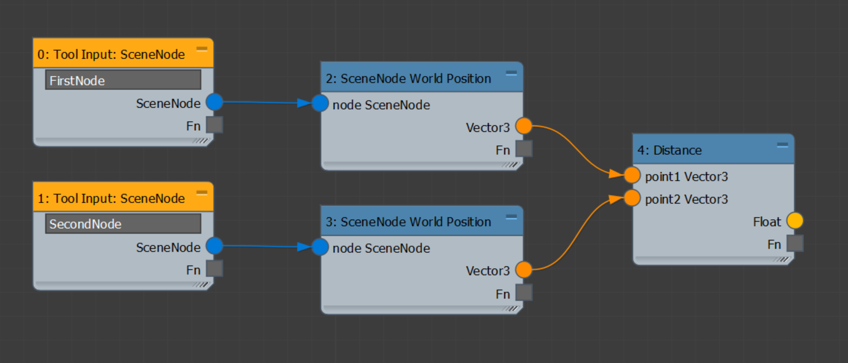
Create a new empty MCG graph. Add two Tool Input: SceneNode operators, and wire these to two SceneNode: World Position operators. Finally, wire these nodes into a Distance operator, which will give us the distance between the two picked scene nodes.
-
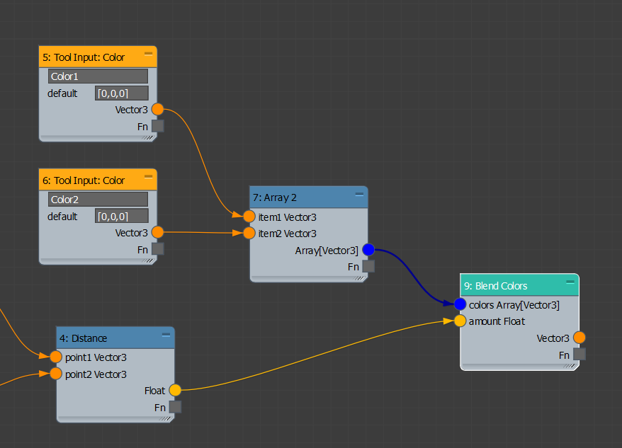
Let's set up the color blend portion of the graph. Add two Tool Input: Color operators, and a Blend Colors operator. Notice that the Blend Colors operator actually takes a single color input in the form of an array. This allows the blend to operate on any number of colors, but it also means we need to package our colors into an array. Add an Array2 operator. As its name implies, it makes an array from two items. Wire the colors into item1 and item2. Wire the Distance output into the Blend Colors amount socket.
-
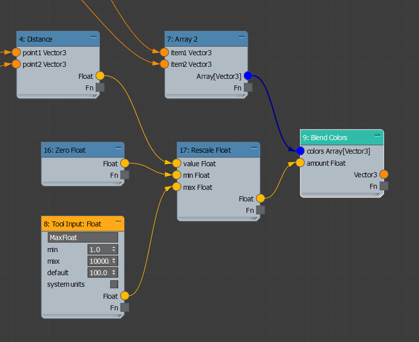
If you select the Blend Colors node and look at the description, you'll see an issue with our graph: the amount value needs to be between 0.0 and 1.0, and our Distance node is returning an arbitrary value that is most likely larger than 1.0. We'll fix this with rescaling. Add a Rescale Float operator, and wire the Distance output into its value input. This operator returns a float between 0.0 and 1.0 that represents the proportion of the input value that is between the specified minimum and maximum. For example, for a minimum of 0 and a maximum of 100, and input value of 50 will result in 0.5. Wire a Zero Float operator into the min value, and a Tool Input: Float into the max. Give it a name and set the default to an appropriate value like 100.0. This will allow the user to specify the maximum distance the controller will respond to. Finally, wire the Rescale Float output into the Blend Colors operator.
-
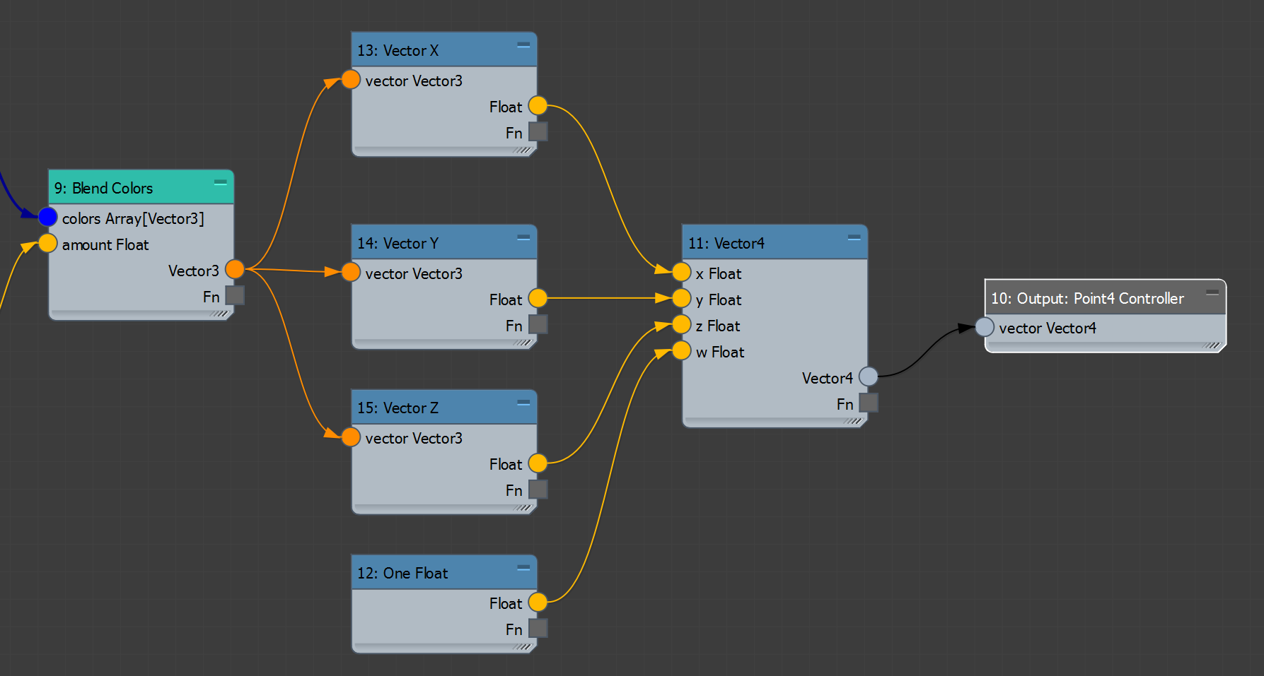
Now we have a second problem - Blend Colors outputs a Vector3 value (representing an RGB color), but Physical Materials take a 4 channel color (RGBA), so we need to find a way to convert to this format. We can do this by simply creating a Vector4 value, wiring the X, Y, and Z values into it from our exiting Vector3 output, and then providing a constant 1.0 value for the Alpha channel, then finally wiring the resulting Vector4 to an Output: Point4 Controller. This part of your graph should look like this:
-
Now we can test the graph. Save your graph as a .maxtool as "MCG_ColorFromDist", evaluate it, and make sure there are no errors. Add three objects to a scene. In the Material Editor, add a new Physical Material, then right-click, and select Show/Hide Slots > Additional Params > Base Color. Drag out the Base Color and select MCG_ColorFromDist. Double-click the Controller MCG_ColorFromDist node in the Material Editor to open the controller dialog. From here you can pick two nodes in the scene and two colors to blend.
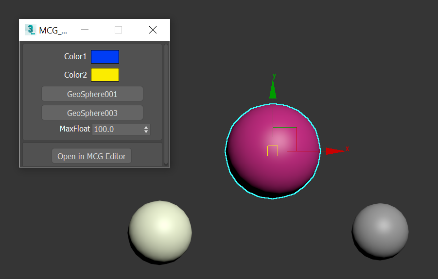
-
Apply the material to the third object, and then move one of the two target objects to see the blend working.
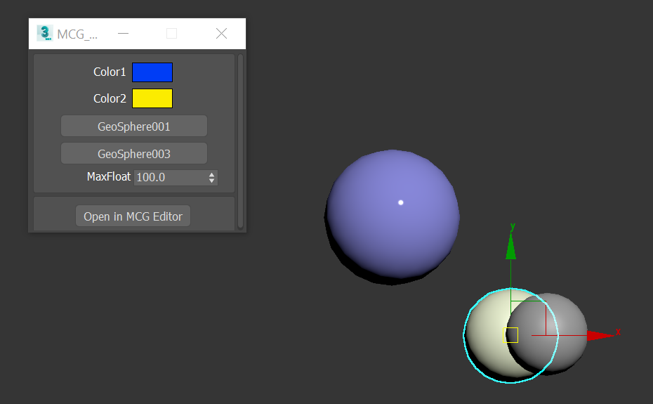
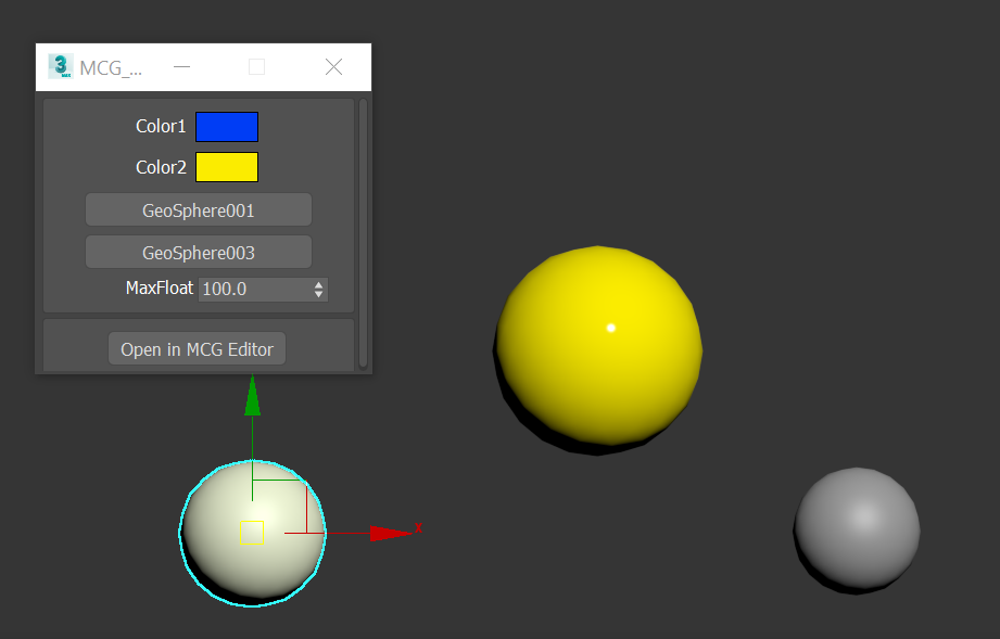
Congratulations, you have built a controller using MCG.