Modifier Basics
In this topic, you learn how to create a MCG modifier tool which splits a mesh's polygons into individual elements which can be scaled and offset.

-
Open the Max Creation Graph Editor: Scripting > Max Creation Graph Editor
-
Add a Output: Modifier node to the graph, either by pressing the X key, typing its name and pressing enter, or by dragging it from the Operator Depot under Outputs > Tools. This is the terminal node of the graph, which places the tool in the Modifier List.

-
Add a Modifier: Mesh (Inputs > Tools) node to access the mesh flowing up the modifier stack. The vertices of this mesh are defined in the tool's local space.

-
With the mesh in hand, use a Split Mesh into Polygons operator (Geometry > Mesh > Polygon) to convert every polygon into its own mesh. A polygon is defined based on the edge visibility between triangular faces in the mesh.

-
To manipulate a given polygon, we'll need to know its current location and orientation. To that effect, we'll use the Mesh Polygon Transforms compound (Geometry > Mesh > Polygon) to obtain the transformation matrices which describe each polygon's location and orientation. This compound uses the average normal of each face and the average position of each vertex in the polygon to compute its transform.

-
We want to expose two inputs to our tool: the "Scale" of each polygon relative to its centerpoint, and an "Offset" vector to move each polygon relative to its starting position on the mesh. Combine these as a single transformation matrix with the Translation Scaling Matrix operator (Math > Matrix).

-
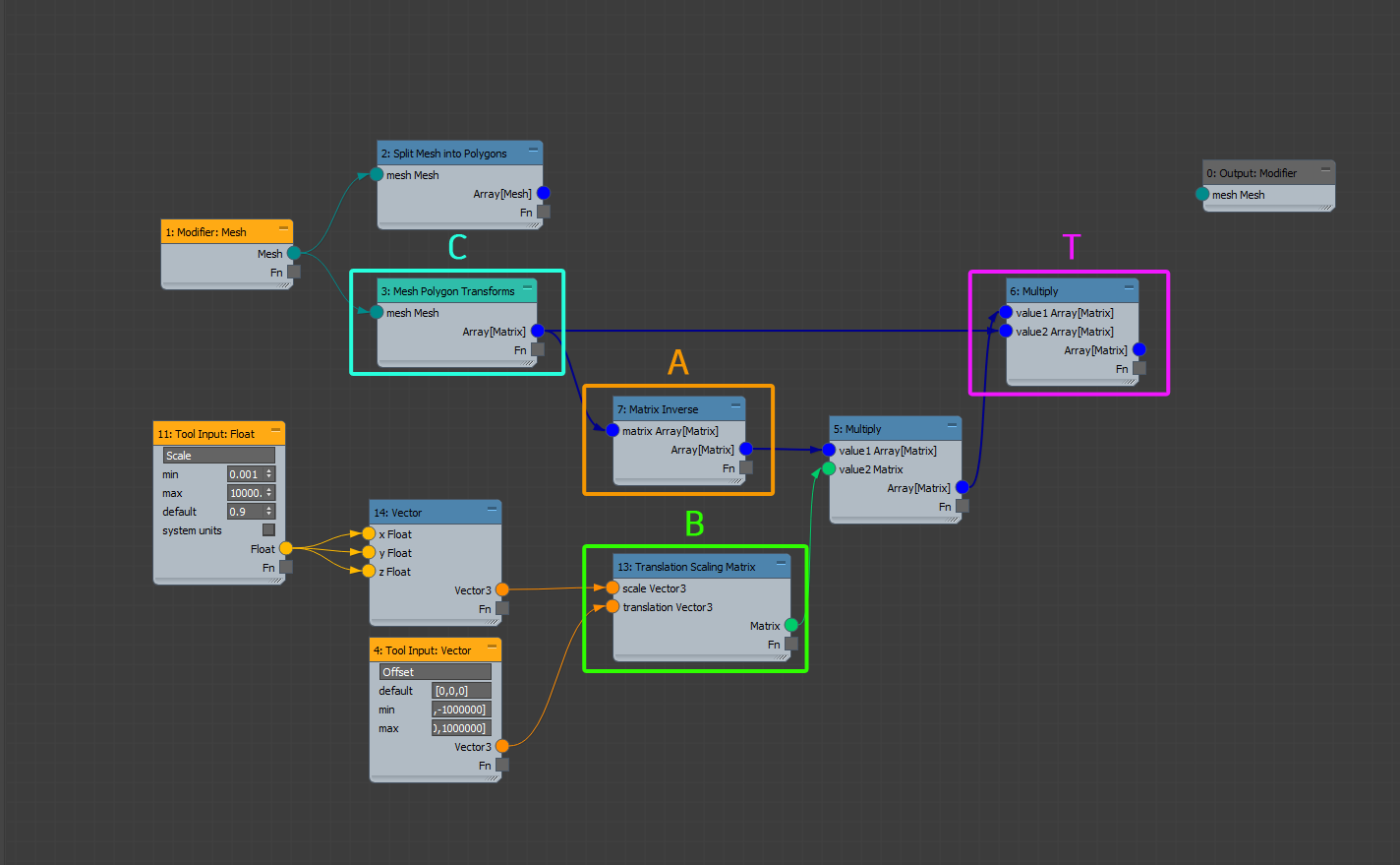
The next step involves a bit of matrix gymnastics, but it's worth the effort. Connect the nodes to replicate the graph below.
Note: Be mindful of your connections into the Multiply nodes; the input order for matrix multiplication matters. Matrix multiplication is generally not commutative, meaning that the result of A * B is generally not the same as B * A.
To get a better understanding of what's going on:

-
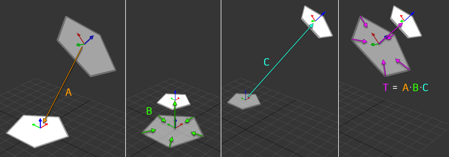
Matrix A is the transform which brings the polygon back to the local origin.
-
Matrix B is the custom transform we've prepared based on the tool's inputs, in this case: a scaling factor and an offset.
-
Matrix C brings the polygon back to its original position. Notice that matrix A is the Matrix Inverse of C (and by extension, C is the inverse of A). Simply put, matrices A and C perform opposite work. We use A and C in order to conveniently apply the transform of B relative to the polygon's center at the local origin.
-
When you multiply matrices, you accumulate the work performed by those matrices (as well as the order of that work), which is why matrix T can be defined as A * B * C.
-
-
Apply the computed transform T to each polygon with the Transform Mesh operator. Then, use the Attach All Meshes operator to combine the result into a single mesh so it can be returned to the Output: Modifier.

-
Press CTRL+S (or File > Save As...) to save the graph.
-
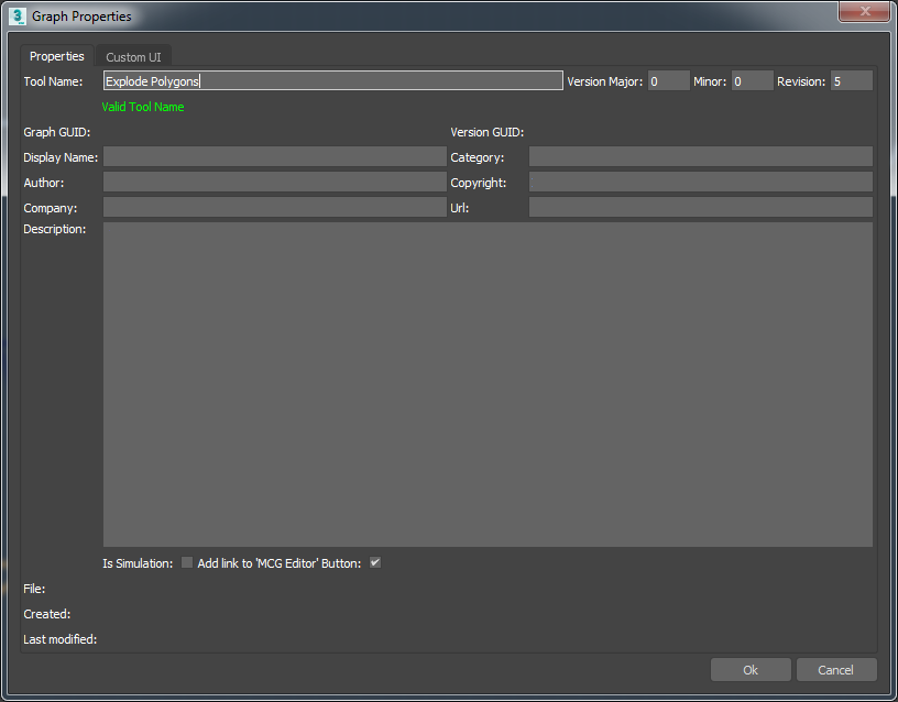
Set the Tool Name to "Explode Polygons" in the Graph Properties dialog, and press Save As.
-
Save your graph to the default Tools location (your user profile
/Autodesk/3ds Max 2018/Max Creation Graph/Toolsfolder).
-
-
Press CTRL+E (or Build > Evaluate) to evaluate the tool and register it into 3ds Max. The Message Log should indicate that the tool was successfully evaluated.
-
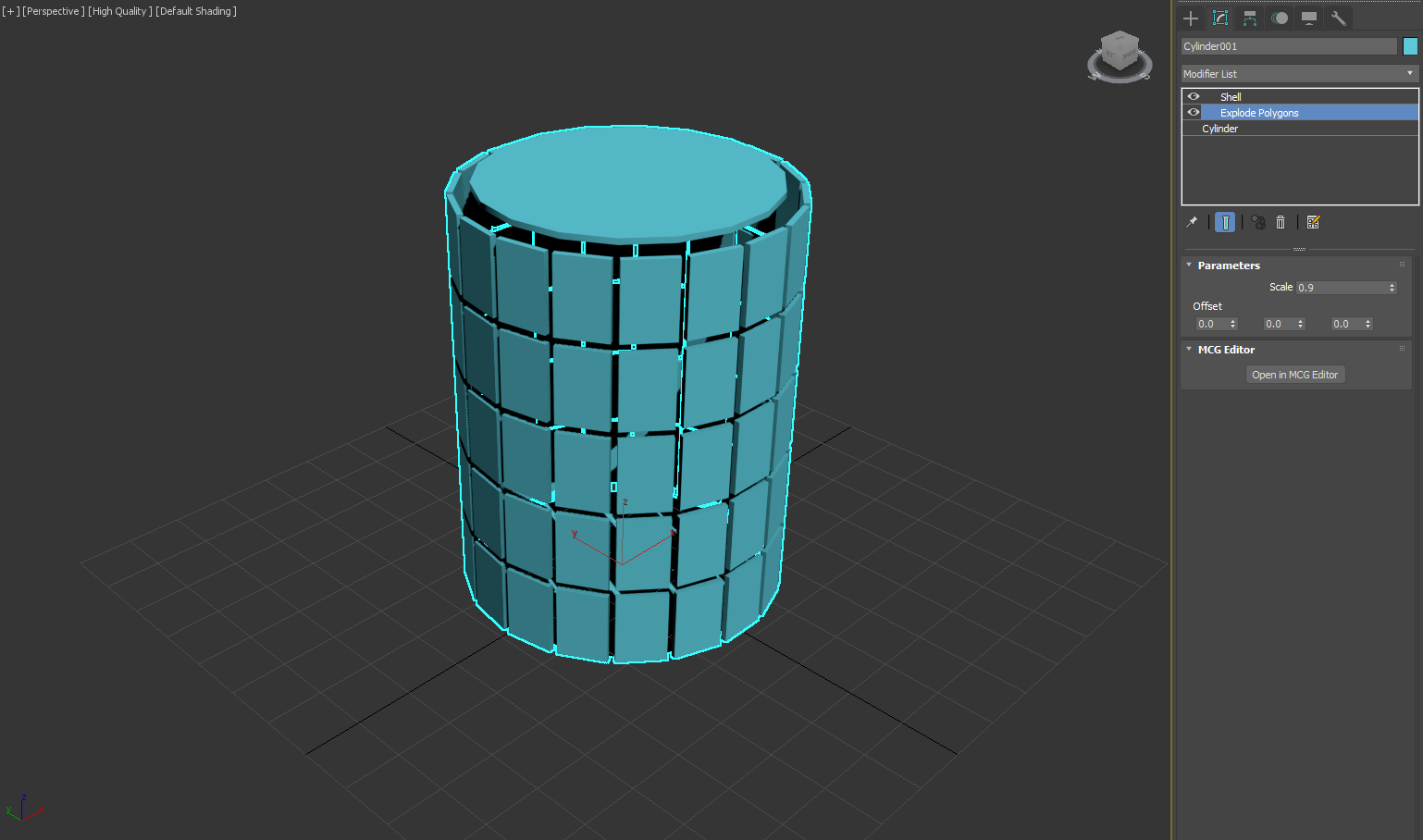
Create a geometry object in your scene, then go to the Modify Tab and add the Explode Polygons modifier. The object's polygons should now all be detached and controllable with the Scale and Offset spinners.
Tip: Add a Shell modifier to provide thickness to each polygon.