How To ... Develop An SVG Polygon Renderer - Part 2
The following is part two of a three parts tutorials series demonstrating the use of MAXScript together with the Vector_Map TextureMap. MAXScript will be used to write an SVG XML file to disk containing polygon entities representing the faces of scene objects to be rendered. The SVG file can be loaded in any Web Browser or rendered to a bitmap using the renderMap() function. For more information about the use of MAXScript to create SVG files, see the Vector_Map TextureMap and MAXScript topic.
In the first part of the tutorial, we output all camera-facing triangle faces of all geometry objects.
In this second part of the tutorial, we will sort the polygons by depth to make sure the faces do not overlap incorrectly.
In the third part of the tutorial, we will add support for material colors and implement lighting using Facets Shading and Blinn Specular Highlights.
Related topics:
Vector_Map TextureMap and MAXScript
NATURAL LANGUAGE
Define a function to sort array values by the 6th array element which will be the Z depth in camera space.
Introduce an array to collect all polygon data to be drawn, so it can be pre-sorted.
Calculate the Z-depth value and collect all necessary data in the new array.
Sort the new array using
qsort()and the new sorting function.Loop through the sorted array and draw back to front.
SCRIPT:
   (
   fn ColorToHex col =
   (
       local theComponents = #(bit.intAsHex col.r, bit.intAsHex col.g, bit.intAsHex col.b)
       local theValue = "#"
       for i in theComponents do
           theValue += (if i.count == 1 then "0" else "") + i
       theValue
   )

   fn compareFN v1 v2=
   (
       if v1[6] < v2[6] then -1 else 1
   )

   local st = timestamp()
   local theFileName = (getDir #userscripts + "\\PolygonRendering.svg")
   local theSVGfile = createFile theFileName
   format "<svg xmlns=\"http://www.w3.org/2000/svg\"\n" to:theSVGfile
   format "\t\txmlns:xlink=\"http://www.w3.org/1999/xlink\">\n" to:theSVGfile

   local theViewTM =  viewport.getTM()
   theViewTM.row4 = [0,0,0]
   local theViewTM2 = viewport.getTM()
   local theViewSize = getViewSize()
   local theViewScale = getViewSize()
   theViewScale.x /= 1024.0
   theViewScale.y /= 1024.0

   local drawArray = #()

   local theStrokeThickness = 1

   gw.setTransform (matrix3 1)
   for o in Geometry where not o.isHiddenInVpt and classof o != TargetObject do
   (
       local theStrokeColor = white
       local theFillColor = o.wirecolor

       local theMesh = snapshotAsMesh o
       for f = 1 to theMesh.numfaces do
       (
           local theNormal = normalize (getfaceNormal theMesh f)
           if (theNormal*theViewTM).z > 0 do
           (
               local theFace = getFace theMesh f
               local v1 = gw.transPoint (getVert theMesh theFace.x)
               local v2 = gw.transPoint (getVert theMesh theFace.y)
               local v3 = gw.transPoint (getVert theMesh theFace.z)

               v1.x /= theViewScale.x
               v1.y /= theViewScale.y
               v2.x /= theViewScale.x
               v2.y /= theViewScale.y
               v3.x /= theViewScale.x
               v3.y /= theViewScale.y

               local theFaceCenter = meshop.getFaceCenter theMesh f
               local theZDepth = (theFaceCenter*theViewTM2).z
               append drawArray #(v1, v2, v3, (ColorToHex theStrokeColor), (ColorToHex theLitFillColor), theZDepth)


                       )--end if normal positive
       )--end f loop
   )--end o loop

   qsort drawArray compareFN

   for d in drawArray do
   (
       format "\t<polygon points='%,%  %,%  %,%' \n" d[1].x d[1].y d[2].x d[2].y d[3].x d[3].y to:theSVGfile
       format "\tstyle='stroke:%; fill:%; stroke-width:%'/>\n" d[4] d[5] theStrokeThickness to:theSVGfile
   )

   format "</svg>\n" to:theSVGfile
   close theSVGfile
   local theSVGMap = VectorMap vectorFile:theFileName alphasource:0
   local theBitmap = bitmap theViewSize.x theViewSize.y
   renderMap theSVGMap into:theBitmap filter:true
   display theBitmap
   format "Render Time: % sec.\n" ((timestamp()-st)/1000.0)
   )
Step-By-Step
Code in *Italic* is the same as in Part 1. Code in Bold is new.
(
fn ColorToHex col =
(
    local theComponents = #(bit.intAsHex col.r, bit.intAsHex col.g, bit.intAsHex col.b)
    local theValue = "#"
    for i in theComponents do
        theValue += (if i.count == 1 then "0" else "") + i
    theValue
)
fn compareFN v1 v2=
(
if v1[6] < v2[6] then -1 else 1
)This function will be used by the qsort() method to compare two elements of our sorting array.
We will be storing the Z-Depth value of each polygon in the 6th element of the array, so this function will get two array items and will return -1 or 1 depending on whether the first one is farther or closer than the second one.
local st = timestamp()
local theFileName = (getDir #userscripts + "\\PolygonRendering.svg")
local theSVGfile = createFile theFileName
format "<svg xmlns=\"http://www.w3.org/2000/svg\"\n" to:theSVGfile
format "\t\txmlns:xlink=\"http://www.w3.org/1999/xlink\">\n" to:theSVGfile

local theViewTM =  viewport.getTM()
theViewTM.row4 = [0,0,0]
local theViewTM2 = viewport.getTM()
local theViewSize = getViewSize()
local theViewScale = getViewSize()
theViewScale.x /= 1024.0
theViewScale.y /= 1024.0
local drawArray = #()This array will be populated with the polygons including vertices transformed into view space, colors to use for Stroke and Fill, as well as the Z-Depth value for sorting.
local theStrokeThickness = 1We will set the Stroke to 1 to be able to better investigate the previous problems at the outlines of the Geosphere.
gw.setTransform (matrix3 1)
for o in Geometry where not o.isHiddenInVpt and classof o != TargetObject do
(
    local theStrokeColor = white
    local theFillColor = o.wirecolor

    local theMesh = snapshotAsMesh o
    for f = 1 to theMesh.numfaces do
    (
        local theNormal = normalize (getfaceNormal theMesh f)
        if (theNormal*theViewTM).z > 0 do
        (
            local theFace = getFace theMesh f
            local v1 = gw.transPoint (getVert theMesh theFace.x)
            local v2 = gw.transPoint (getVert theMesh theFace.y)
            local v3 = gw.transPoint (getVert theMesh theFace.z)

            v1.x /= theViewScale.x
            v1.y /= theViewScale.y
            v2.x /= theViewScale.x
            v2.y /= theViewScale.y
            v3.x /= theViewScale.x
            v3.y /= theViewScale.y
local theFaceCenter = meshop.getFaceCenter theMesh f
local theZDepth = (theFaceCenter*theViewTM2).z We will sort by the distance of the Face Center to the viewer, so we need to get the Face Center position in the World Space first, then transform it into the View space.
The Z coordinate will be a negative value that will be lower the farther the point is from the viewer.
We will use this in our sorting function called by qsort() .
append drawArray #(v1, v2, v3, (ColorToHex theStrokeColor), (ColorToHex theLitFillColor), theZDepth)Instead of outputting directly to the SVG file, we will collect each polygon in the drawArray variable, including the three vertices in screen space, the Hexadecimal colors of the polygon's Stroke and Fill, and the Z-Depth value calculated above.
        )--end if normal positive
    )--end f loop
)--end o loop
qsort drawArray compareFNNow, we can sort the drawArray according to the distance stored in the 6th element (the Z-Depth value).
We want polygons with lower Z-Depth (larger negative numbers) to be drawn first, thus implementing the "Painters Algorithm" where the drawing is performed back to front relative to the camera.
for d in drawArray do
(
    format "\t<polygon points='%,%  %,%  %,%' \n" d[1].x d[1].y d[2].x d[2].y d[3].x d[3].y to:theSVGfile
    format "\tstyle='stroke:%; fill:%; stroke-width:%'/>\n" d[4] d[5] theStrokeThickness to:theSVGfile
)
This for loop will output the sorted polygon data to the SVG file.
This is very similar to the previous version of the code, but we do this in a second loop and read the values from the sorted array.
format "</svg>\n" to:theSVGfile
close theSVGfile
local theSVGMap = VectorMap vectorFile:theFileName alphasource:0
local theBitmap = bitmap theViewSize.x theViewSize.y
renderMap theSVGMap into:theBitmap filter:true
display theBitmap
format "Render Time: % sec.\n" ((timestamp()-st)/1000.0)
)
Using The Script To Render Geometry
Let us test the changes to the script on the same examples as in Part 1 to see the difference.
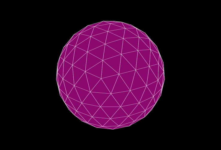
As you can see, the problems at the edges of the Geosphere have been solved by the new sorted drawing approach.
It matches the results seen in the viewport using "Consistent Colors + Edged Faces" drawing mode pretty closely.

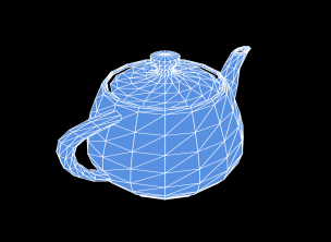
Let us increase the Stroke Thickness to 2 and render the Teapot primitive from the Part 1:
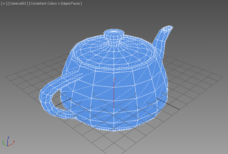
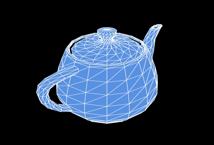
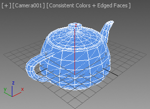
Let us resize the viewport and look at the result:
Rendering the problematic setup from the first part also produces correct results now:
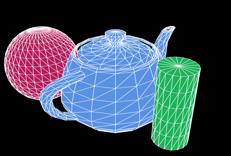
Because we are culling the backfaces, it is possible to see the Sphere through the gap between the Teapot's Body and Lid.
By remarking the backface culling line,
-- if (theNormal*theViewTM).z > 0 dowe can render all polygons of all objects without any culling. The rendering will take approximately twice as long, but the sphere will be correctly occluded:
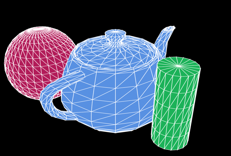
In the third part of the tutorial, we will add material color and lighting support to the script to produce faceted rendering with diffuse shading and Blinn specular highlights.