Bump Mapping
Bump mapping is a technique that enables a surface to appear wrinkled or dimpled without the need to model these depressions geometrically. Rather, the surface normal is perturbed according to the information in the bump map to create variations in the smooth surface.
A 2D bump map is applied to the surface of an object. The space along the surface is called the UV space. The 2D bump map can be thought of as its own surface with bright areas as hills and dark areas as valleys. You can then define a gradient on the surface, which can be thought of as the downhill or uphill directions. This gradient of values gives a direction in UV space where you can perturb the surface normal. If you have a bump in a texture, for example a steep uphill, then you can perturb the normal to make it look like there is a steep hill. Given the gradient in UV space, you need to determine what direction in 3D (XYZ) space to perturb the corresponding normal. The bump basis vectors are used for this purpose. These are the vectors that represent the UVW axes of the texture in 3D and can be used to perturb the normal.
To understand how this is done, look at the following sample code. The method responsible for returning the perturbed normal is Texmap::EvalNormalPerturb(). The code below is from \\MAXSDK\\SAMPLES\\MATERIALS\\CHECKER.CPP, but all the other 2D textures use a similar approach.
Point3 Checker::EvalNormalPerturb(ShadeContext& sc)
{
   Point3 dPdu, dPdv;
   if (!sc.doMaps) return Point3(0,0,0);
   if (gbufID) sc.SetGBufferID(gbufID);

   uvGen->GetBumpDP(sc,dPdu,dPdv);
   Point2 dM = uvGen->EvalDeriv(sc,&mysamp);

   returnd M.x*dPdu+dM.y*dPdv;
}
The first significant line related to bump mapping is:
uvGen->GetBumpDP(sc,dPdu,dPdv);This method of UVGen gets the bump vectors. You can also get the bump vectors directly from the method ShadeContext::DPdUVW(), although these are not be affected by the UVGen transformations.
In this case, all the coordinates are coming through UVGen. You must use GetBumpDP() because the UVGen has rotated things around or has transformed the bump vectors to a new position. Basically, the UVGen has rotated the UV space into another position locally, so this method gets the bump basis vectors, which are really the U and V axes in 3D space (unit vectors in the U direction and the V direction, but in 3D space).
The next line computes dM. This is the derivative of the function across the pixel. This is the rate of change of the function in the U direction (dM.x) and the V direction (dM.y). If this is a flat function, both of these are zero. If the function is increasing in U but is constant in V, then the value in the U direction corresponds to how fast it is changing while V is still zero. Thus, dM can be thought of as the gradient or how fast things are changing up and down.
Point2 dM = uvGen->EvalDeriv(sc,&mysamp);Next, you need to compute the perturbation to the normal. This can be thought of as a small vector that is added to the end of the existing normal to move it a little bit. There are several ways to do this. The common textbook algorithm (Blinn's algorithm for bump mapping) is not used by the 3ds Max textures. Rather, the calculation shown below is simpler and faster with no visual difference. To compute the perturbation to apply to the normal, the following code is used:
return dM.x*dPdu+dM.y*dPdv;This takes the sum of the U component (dM.x) multiplied by the U basis vector (dPdu) and the V component (dM.y) multiplied by the basis vector in the V direction. This gives the change (perturbation) to the normal as a unit vector.
The result of EvalNormalPerturb() (the perturbation to apply to the surface normal) is used by 3ds Max as follows: Outside the procedural texture, for example in the Standard material, the value returned is added to the surface normal. The normal is then re-normalized (made a unit vector again). This altered normal results in the surface appearing bumped when rendered.
Tangents and Bitangents Generation
The following example shows how the tangent and bitangent vectors are calculated in Nitrous, Quicksilver, and Scanline.
Calculating Tangents and Bitangents for Vertices on a Triangle Face
The inputs are pos (vertex positions), norm (vertex normals), and uv (texture coordinates).
void CalculateTangentsBitangents(
Point3 pos[3], Point3 norm[3], Point3 uv[3],
Point3 tangent[3], Point3 bitangent[3])
{
    float uv1x = uv[1].x - uv[0].x;
    float uv2x = uv[2].x - uv[0].x;
    float uv1y = uv[1].y - uv[0].y;
    float uv2y = uv[2].y - uv[0].y;
    float uvk = uv2x * uv1y - uv1x * uv2y;

    Point3 v1 = pos[1] - pos[0];
    Point3 v2 = pos[2] - pos[0];

    Point3 faceTangent;
    if (uvk != 0) {
       faceTangent = (uv1y * v2 - uv2y * v1) / uvk;
    } else {
       if (uv1x != 0) faceTangent = v1 / uv1x;
       else if (uv2x != 0) faceTangent = v2 / uv2x;
       else faceTangent = Point3(0.0f, 0.0f, 0.0f);
    }
    Normalize(faceTangent);

    Point3 mapNormal = CrossProduct(uv[1] - uv[0], uv[2] - uv[1]);
    bool flip = mapNormal.z < 0;

    for (int i = 0; i < 3; ++i)
    {
     // Make tangent perpendicular to normal
     tangent[i] = faceTangent - DotProduct(norm[i], faceTangent) * norm[i];
     Normalize(tangent[i]);

     bitangent[i] = CrossProduct(norm[i], tangent[i]);
     if (flip) bitangent[i] = -bitangent[i];
    }
}
Smoothing
If a vertex is shared among multiple faces, and the texture coordinate and smooth group of the vertex are the same among all the faces, the tangents and bitangents calculated for this vertex on each face is accumulated and normalized to form the final tangent and bitangent of the vertex.
Normal Bump Modes
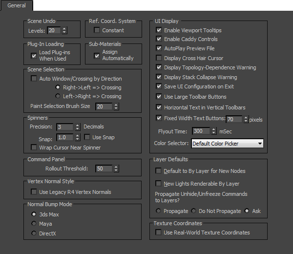
3ds Max supports the following normal bump modes: 3ds Max Mode, Maya Mode, and DirectX Mode. You can select a normal bump mode in the General tab of the Preferences Settings dialog, which can be accessed by selecting Customize  Preferences. The calculation of tangents and bitangents vary based on the normal bump mode.
The following figure shows the three normal bump modes in the Preferences Settings dialog.
These normal bump modes are explained in the following table.
| Mode | Description |
|---|---|
| *3ds Max Mode * | The face normal that is always perpendicular to the triangle face is used in the calculation. During pixel shading, the tangent and bitangent interpolated from the triangle vertices are used in the normal bump calculation. |
| *Maya Mode * | The vertex normal that considers smooth group and which can be tuned using the Edit Normals modifier is used in the calculation. During pixel shading, the tangent and bitangent interpolated from the triangle vertices are orthogonalized against the normal before the normal bump calculation. |
| *DirectX Mode * | The vertex tangent and bitangent are perpendicular to the vertex normal. During pixel shading, the tangent and bitangent interpolated from the triangle vertices are used in the normal bump calculation. |