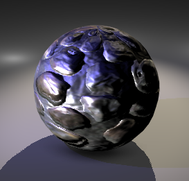
Displacement and Tessellation Factor
You can add displacement to your object by connecting a height (displacement) map to the Displacement attribute of the Material node.
To visualize tessellation and displacement in Viewport 2.0, you must be working in the DirectX 11 environment and have the dx11Shader.mll plug-in enabled. For more information, see Using DirectX 11 with Viewport 2.0.
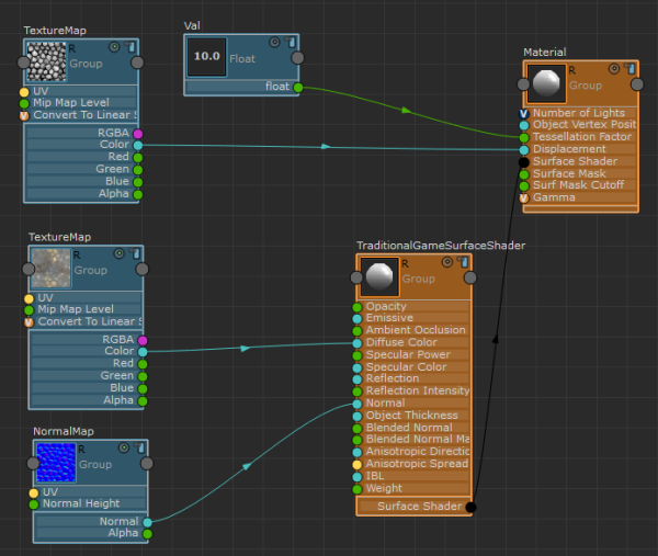
The following graph demonstrates how to connect your displacement and tessellation attributes:
-
Create a Texture Map node for your displacement map, and connect its Color attribute to the Displacement attribute of the Material node.
-
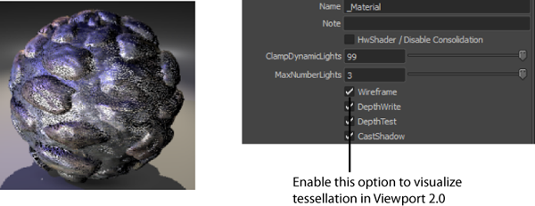
Create a Float node and connect it to the Tessellation Factor attribute of the Material node. Use the float value to adjust the amount of tessellation for your object. To visualize the amount of tessellation in Viewport 2.0, select the Material node and enable the Wireframe option in the Attribute Editor. When setting this float value, you should consider how dense your mesh is; if your mesh already has a lot of faces, you can use a lower value such as 2 or 3. If your mesh does not have a lot of faces, you may need to use a higher value. When this value is set too high, your scene may slow down; therefore, you should experiment with different values to find the best value for your purposes.
-
Create a Normal Map node and connect it to the Normal attribute of the TraditionalGameSurfaceShader as shown in the graph. This step is necessary because when you displace the vertices of your object, the normals become incorrect for the new positions of the vertices. You can correct this issue by connecting a normal map with the correct normal values to your network.
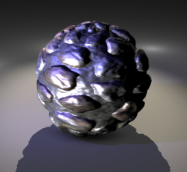
Vector displacement map (PNAEN Displacement Map)
Create this node by selecting: Hw Shader Nodes > Textures > PNAEN Displacement Map in the ShaderFX editor.
In the Material node Attribute Editor, the Displacement / Options attribute allows you to choose between providing a grayscale map or a vector displacement map.
To visualize tessellation and displacement in Viewport 2.0, you must be working in the DirectX 11 environment and have the dx11Shader.mll plug-in enabled. For more information, see Using DirectX 11 with Viewport 2.0.
The following graph demonstrates how to connect your normal and height maps:
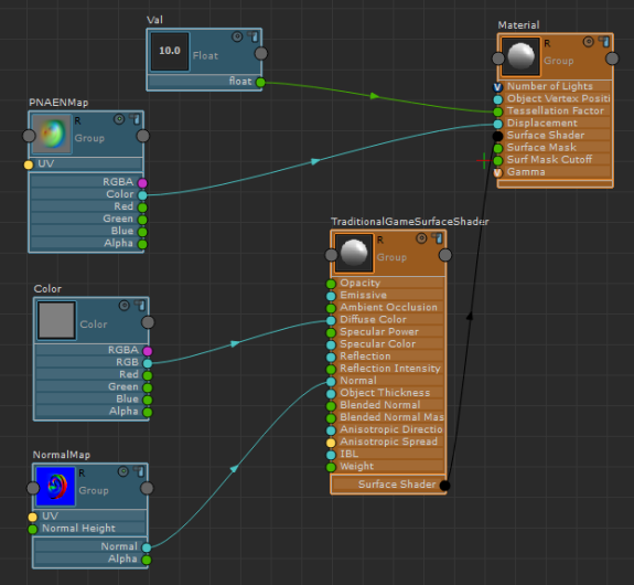
- Create a PNAEN Displacement Map node (Hw Shader Nodes > Textures > PNAEN Displacement Map) and connect its Color attribute to the Displacement attribute of the Material node.
- Create a Float node (Hw Shader Nodes > Values > Float) and connect it to the Tessellation Factor attribute of the Material node.
- Create a Normal Map node (Hw Shader Nodes > Textures > Normal Map) and connect it to the Normal attribute of the TraditionalGameSurfaceShader node.
- Select the Material node and adjust the following attributes in the Attribute Editor.
- Set Displacement / Options to VectorDisplacementTangent or VectorDisplacementWorld, depending on whether your map is in tangent or world space.
- Select the correct displacement axis from VDM_CoordSys / Options. The axis is determined by the application from which you generated the vector displacement map, for example, Mudbox.
- Adjust the DisplacementMultiplier. If the application from which the vector displacement map was created has the same world scale as Maya, then you can leave this value at 1. Otherwise, you must adjust this value.
- Set the Displacement Offset to 0 for vector displacement maps (and 0.5 for greyscale displacement maps).
This attribute controls the base value for your displacement.
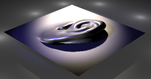
For example, if the offset is set to 0.5, a gray color is not displaced. A black color would produce an indentation. A white color would extrude.
Likewise, if the offset is set to 0, a black color is not displaced. An offset of gray (0.5) would extrude half as much as an offset of 1.0 (white). Indentations do not occur.
Offset Bump Map
Create this node by selecting: Hw Shader Nodes > Textures > Offset Bump Map in the ShaderFX editor.
The Offset Bump Map is also called a parallax map. You can connect both a normal map and an additional height map to this node to give a better representation of depth.
The following graph demonstrates how to connect your normal and height maps:
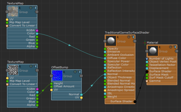
- In the Offset Bump Map Attribute Editor, connect your normal map.
- Create a Texture Map node for your height map and connect its Red channel to the Height attribute of Offset Bump Map.
- Create a second Texture Map node for your diffuse map and connect it to the Diffuse Color attribute of TraditionalGameSurfaceShader.
You can adjust the height of the bumps by selecting the Offset Bump Map node and adjusting the OffsetAmount attribute in the Attribute Editor.
