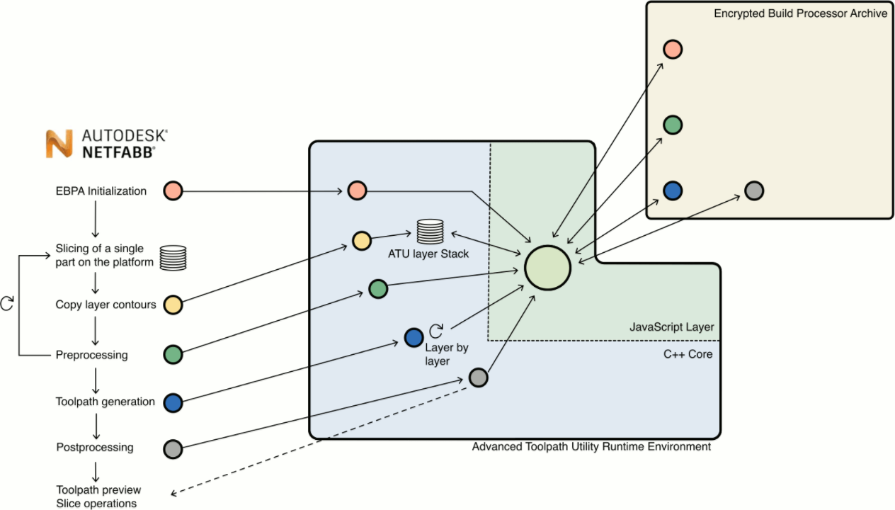
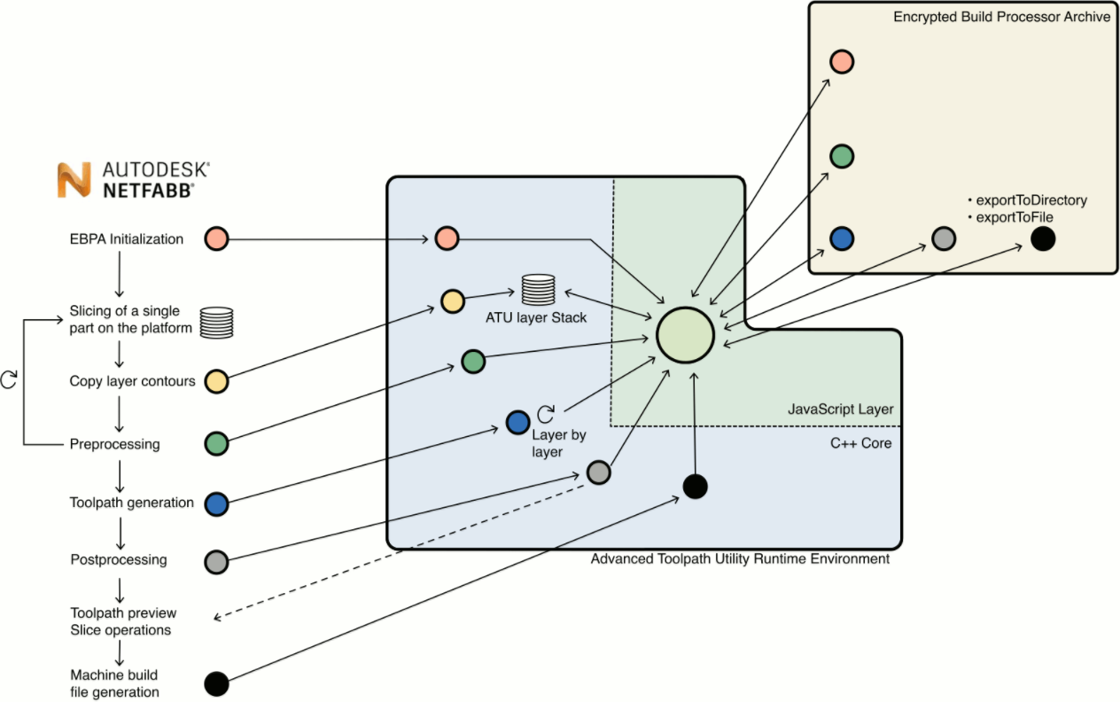
With the ability to change layer contour data and to create toolpaths and machine buildfiles, the ATU buildstyle processor can be used for various tasks. To ensure a consistent behavior across different host applications (eg. Autodesk® Netfabb®), a strict integration workflow for host applications was set up to guarantee identical processing results. It is important for every ATU developer to be aware of this workflow, because it influences operation order and data management of ATU JavaScript projects:

|
The Netfabb integration is taken as an example:
|
ATU-side of this workflow
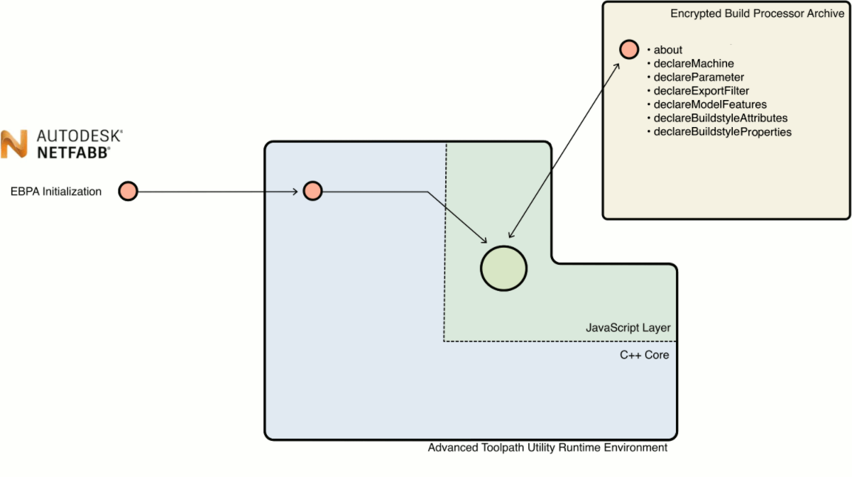
Initialization
The initialization makes all files of an EBPA archive available and calls the following javascript functions:
| about | This function is called to get a description and copyright informations from used EBPA files. |
| declareBuildstyleAttributes | Buildstyle attributes are used to add parameters to the toolpath. They have to be declared at this function. |
| declareExportFilter | All available export formats are listed up here, so that the host application can choose between them. |
| declareMachine | The buildstyle sets up machine and materials for EBPA calculations. Since buildstyles can support more than one material, the host application will query a list of supported materials, which are specified here. |
| declareModelFeatures | Some special operations can be turned on or off here (Hull/Core generation, shadow polygon etc.) |
| declareParameters | Each buildstyle can have its own set of parameter groups and parameters. This function sets up available groups and parameters. |
| declareBuildstyleProperties | Define arbitrary additional properties. These properties can be read by the host program (e.g. ATU or Netfabb) directly. There are some predefined properties such as adsk_main.custom_thickness_allowed. |
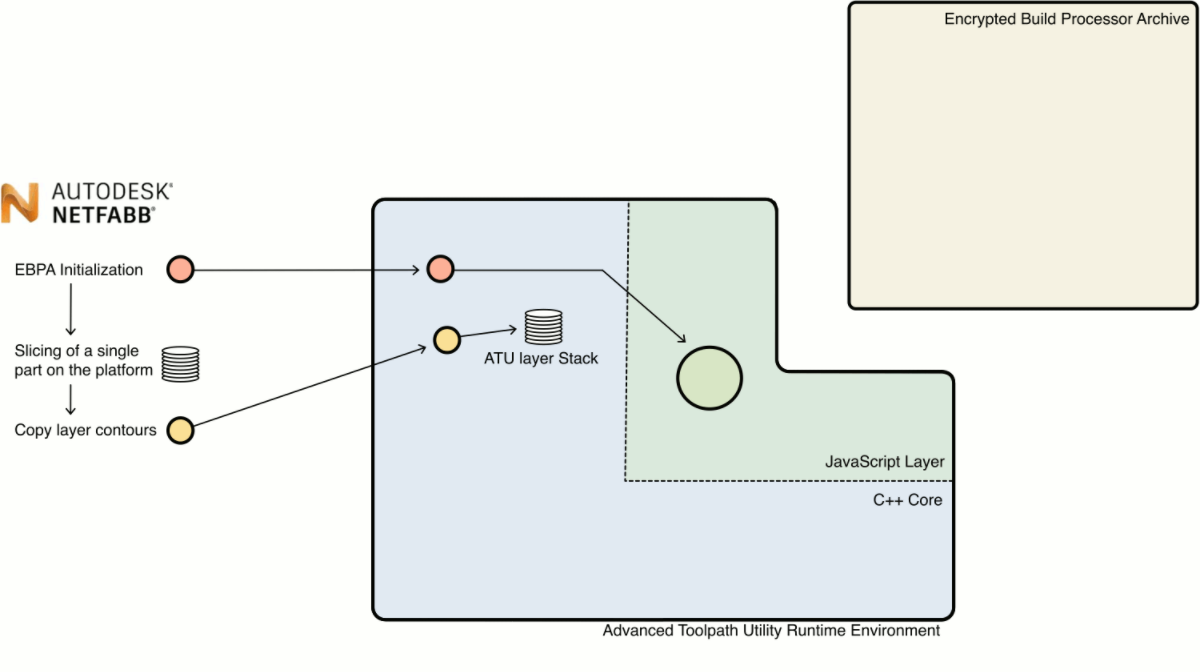
Layer contour data
Any slicer can be used with the Advanced Toolpath Utility runtime. In case of Netfabb, the Netfabb slicer module creates layer contour data from each part on the platform. These contours are transferred to the ATU runtime and they are saved to an ATU layer stack. This layer stack is the central database for all contours and toolpaths. All following operations will query, add, modify or delete data on this central data storage.
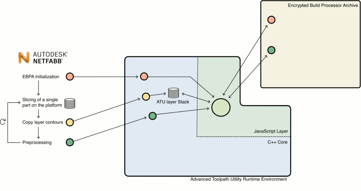
Preprocessing
At this stage, customized JavaScript code can be used to analyze, add, modify or delete layer contour data from a part and its supports.
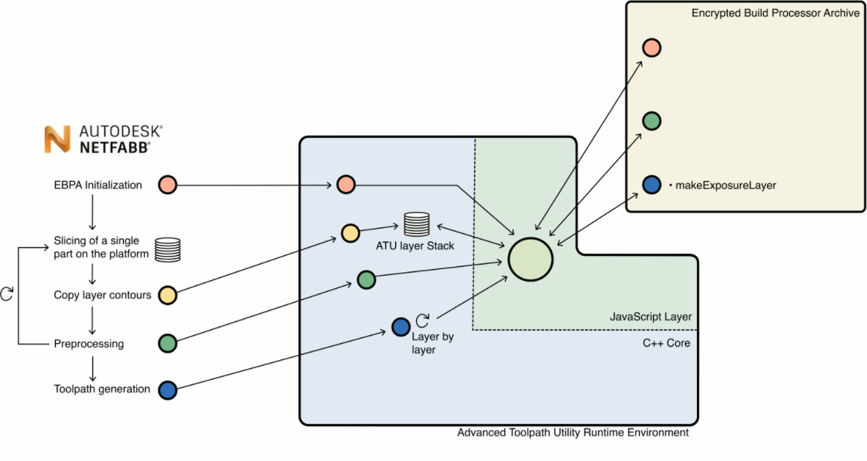
Toolpath generation
Toolpaths are generated by a thread at the ATU runtime environment. For every layer the makeExposureLayer javascript function is called to generate toolpaths for each layer.
Postprocessing
The postprocessing step is the first place, where contours and toolpaths of all parts and all layers are available. It is commonly used to create the overall processing order of all toolpath vectors. The postprocessed toolpath data can be used to create toolpath previews or it can be used for further processing at Netfabb slicing.
Machine buildfile creation
Similar to the postprocessing step, all toolpaths of all layers can be accessed here to generate machine/vendor-specific buildfiles.
Workflow impacts on ATU developers
- At the preprocessing phase, the ATU program has garanteed access to contours of a single part only, because parts are added one after the other.
- Toolpath generation is done multithreaded and the Javascript implementation is called once for each layer. The processing order of layers is managed by a thread and it is not safe to access toolpath data from other layers (but it is safe to access contour data from other layers, as they are generated while layer contours are copied or at the preprocessing step)
- Toolpaths are generated for single parts. The makeExposureLayer function only has access to contours of this single part.
A laser index can be added to the toolpath as an attribute.
Common tasks
Preprocessing support structures of a part
ATU has built-in functions to merge support structure with the part, if they collide. These calculations are done at the preprocessing step.
Getting the platform dimensions
The final layer stack is filled part by part. The dimension of all parts can be calculated step by step at the preprocessing step.
Query data from other layers
It is not safe to query toolpath data from other layers while in multi-threaded toolpath generation step. This data is not guaranteed to be available. Contour data is always available at the toolpath processing step and can be used.
Define start and end positions for toolpaths on each layer
These positions can be determined at the preprocessing step. It is possible to add layer attributes to pass these coordinates to the toolpath creation step.
Create an optimized order for toolpath vectors
The postprocessing step is the right place to go. At this step, all toolpaths of all parts are generated, and it is possible to access these.
Create toolpaths for variable layer thicknesses
Layer thicknesses must be a multiplier of the ATU layer thickness, which will be the thinnest possible layer thickness. Layer attributes can be used to declare the current layer thickness and toolpaths are generated once per "layer pack".
Moving away from printing a platform layer by layer
For some manufacturing methods it makes sense to print several layers at a certain area and then move back to a layer underneath to start printing several layers at another area of the platform. Again, layer and toolpath attributes can be used to create processing groups, that are used at the export step to create the buildfile. It might be necessary to iterate through layers more than once.