Simulation-based STL files can be exported from completed part-scale thermo-mechanical simulations of powder bed builds. There are two primary reasons for exporting STL files:
- Creating a compensated STL- a compensated STL, using a negative warp factor, inverts the simulated displacements and warps the reference STL geometry by those values, multiplied by the warp factor. Printing compensated STLs from an accurate simulation should result in reduced distortion, as the compensated STL should distort into the desired shape.
- Creating a warped STL - a warped STL, using a positive warp factor, applies the simulated displacements directly to the reference STL geometry by those values, multiplied by the warp factor. This creates an STL representation of the simulation results. This type of file can be used for model and material validation or to check to see if the distorted part fits within a part assembly.
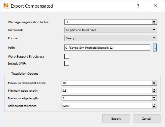
Warpage magnification factor
This specifies the value to multiply all simulated displacements applied to the reference geometry. Negative values are used to create compensated STLs and positive values are used to create distorted STLs.
- Compensation factors: Allowable values are between -0.01 and -99. Typical values fall between -0.5 and -1. A value of -1 would perfectly invert predicted distortion. Compensation factors should account for both the error of the model and the fact that the compensated model will not distort exactly as the original model did, due to the change in geometry.
- Distortion factors: Allowable values between 0.01 and 99. A value of 1 would produce an STL file with the same displacements predicted by the model, useful for assembly fit or validation. Greater or lesser values can be used to exaggerate or reduce the predicted distortion, for analysis of how the part develops distortion.
Increment
Specify which simulation increment to produce the warped STL from:
- All parts on build plate (file name includes the Pre_Removal string)
- After removal from build plate (file name includes the Post_Plate_Removal string)
- After removal from build plate and support structure removal (file name includes the Post_Support_Removal string)
Warpage occurs after the part has been cooled to the final temperature and any optional heat treatment schedule. The last option, after removal of build plate and supports, is available only if support structures are present. A warped STL should only be created from this final increment if on the , Structural Plasticity has been set to On. Otherwise, the excessive distortion after build plate removal will create an overly warped or compensated STL file.
Format
Choose either the Binary format for a smaller file, or ASCII, which produces a human-readable file.
Path
Specify a destination directory for the warped STL. You can use the browse button at the end of this field to select a directory.
Checkbox Options
Select Warp Support Structures if you want the exported STL file to include all support structures in the model. The warpage magnification factor will be applied to the support structures as well as to the part or parts. This option works for the Pre_Removal or Post_Plate_Removal option, and is intended for use with solid volume supports. Lattice or thin wall supports should be regenerated for the compensated STL.
Select Include 3MF if you want a file in 3MF format to be exported along with the STL file. The 3MF files created have improved connectivity and are compatible with the 3MF color functionality.
Tessellation Options
Maximum refinement levels
Specify the maximum number of times an edge can be subdivided. Increasing this value will provide more accurate representation of the modeled distortion, but will result in slower file generation and a larger STL file. For large, complex geometries it is recommended to decrease this from the default value.
Minimum and maximum edge length
Specify the shortest and longest edges allowed in the exported STL, respectively. Decreasing either edge length will take longer to export and produce a larger STL file. Increasing the allowable edge lengths will produce a smaller STL file, but may result in a poorer representation of the model results.
Refinement tolerance
Set a value to indicate how accurately the warped STL must represent the actual simulation results. Lower tolerance values will produce more accurate results, but at the expense of larger files and slower generation times.
When you click the Export button in the lower right, four files are exported to the destination specified as the STL export path, which is the project folder by default:
- <part_name>_Pre_Removal#.in, the input file which is sent to the executable.
- <part_name>_Pre_Removal#.out, a text file that records numeric values about the simulation.
- <part_name>_Pre_Removal#.stl, the exported STL file.
- <part_name>_Pre_Removal#.wrpsimsignal, a file used by the solver to handle any warning and error messages.
In these file names, # is replaced by the warpage magnification factor. If the files are exported from the increment after build plate removal, the Pre_Removal string is replaced by Post_Plate_Removal; If support structures are present, and the files are exported from the final increment, after build plate and structure removal, the file name includes the string Post_Support_Removal.