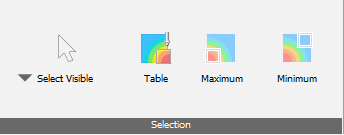
Controls on this panel allow users to investigate and extract temperature, displacement, and other simulation results for specific points or regions of a part, build plate, or support structure. Start by choosing how to select points:
- Select Visible to select points only on visible surfaces when using the rectangular area select option. When individual points are selected, they are always selected on the visible surface.
- Select Through to select all points included when the selected area is projected through the model. This selection method only applies to the rectangular selection window.
Selected points have bright magenta markers. Several point selection methods are available:
- Click on a single point of interest. If you click on another point, the first one is deselected.
- Ctrl-click to select a series of points on a surface.
- Hold down the left mouse button and draw a rectangular window around a region of points.
Points are deselected if you switch from one selection method to another, or select a rectangle outside the model.
In the Browser Results, a Selected points node is created to save selected points with the project, so the points and Result Probe results are retained between sessions.
Click
Table
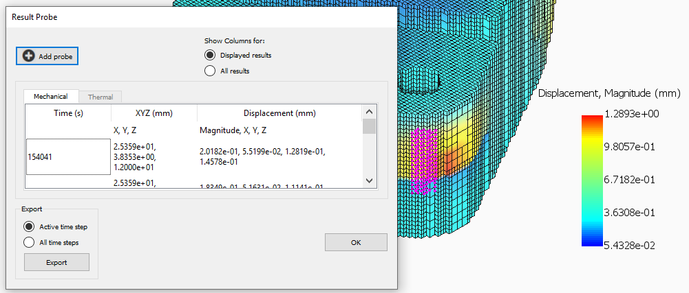
 when you want to see the numeric values for selected points. The
Result Probe table opens, as in the figure below, which shows only the
Displayed results, Displacement in this case, for the points selected in the figure, just to the right of the open dialog. If you select
All results, the table expands to display all available results for each selected point. You can expand the dialog or scroll to see additional data columns.
when you want to see the numeric values for selected points. The
Result Probe table opens, as in the figure below, which shows only the
Displayed results, Displacement in this case, for the points selected in the figure, just to the right of the open dialog. If you select
All results, the table expands to display all available results for each selected point. You can expand the dialog or scroll to see additional data columns.
If you know the coordinates of a point, click Add probe and enter the X, Y, and Z values. If the values you enter are outside the bounds of the part at the displayed increment, you will see a warning message.
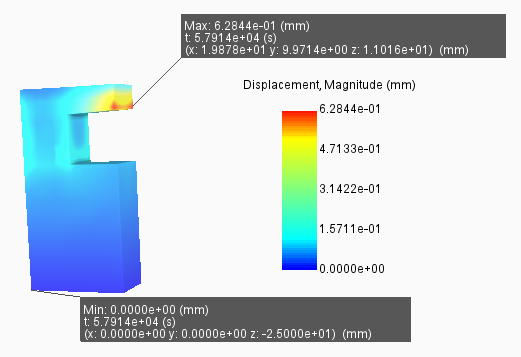
In the Selection panel, you can click Maximum and Minimum buttons to identify and label the points with maximum and minimum values of the displayed attribute. The figure below shows an example for displacement.
In the Result Probe dialog, you can use the Export controls to export the Result Probe table values in CSV format for use in spreadsheets, plots, and other forms of post-process analysis. Choose to export values for only the displayed increment (time step), or for the entire simulation.