Recoater tolerance is the measure of the minimum allowable clearance between the point of maximum upward deflection and the recoater blade for each group of simulated layers. It is expressed as a percentage of the depth of the powder layer. After each simulated layer group the recoater clearance percentage is calculated. If the recoater clearance falls below the set recoater tolerance value, a warning is issued. For instance, setting the recoater tolerance to 80% means that the built part can deflect upward into a maximum of 20% of the new layer before a warning is written to the log files. The following figures can help clarify this concept.
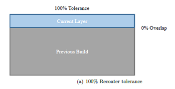
In Figure a, 0.040 mm is allocated for the fusion of the next layer, and there is 0.040 mm on top of the build, which results in a 100% recoater clearance.
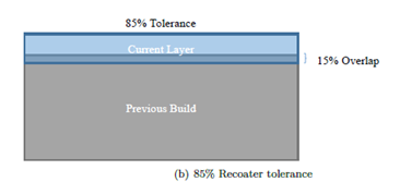
In Figure b, upward distortion of the previous build has taken up 0.006 mm or 15% of the powder thickness, which results in 85% of clearance remaining. This would be acceptable if your recoater tolerance was set to a value of 80%.
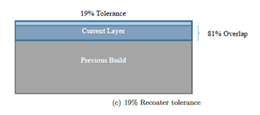
In Figure c, there is a 0.0321 mm build overlap, taking up 81% of the layer thickness. As a result, only 19% recoater clearance remains and the system issues a warning message, as the tolerance is well below the set threshold of 80%.
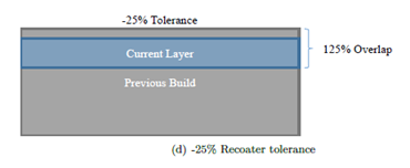
In Figure d, the build of 0.050 mm exceeds the entire recoater clearance of 0.040 mm for the current layer, so it returns a warning and a calculated interference of -25%. This level of upward distortion would almost certainly result in recoater blade damage.