Options and their function explained
Polyline supports are like fences. They are often used to complement volume support, or to trace sharp downward-facing edges that would otherwise go unsupported.
|
Polyline type |
Sets the type of polyline. 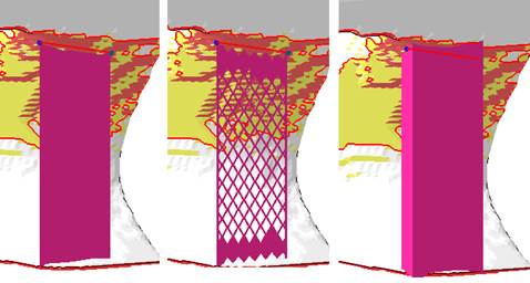 From left: Open wall, open structure, closed wall |
|
|
Distance to part |
A stand-off distance between the end of supports and the part surface they connect with. Can be negative to sink support structure tips into the part if necessary. |
|
|
Smoothing distance |
Determines how many steps will be used to smoothen a polyline. The smaller the distance, the stronger the smoothing and the more triangles will be used. |
|
|
Smooth curves |
Switches the drawing of the resulting polyline supports through the placed anchors between discretely angled and continuously curved. |
|
|
Line width |
Specifies the thickness of a solid wall. |
Solid wall only |
|
|
Support entities can be made conical with a wall angle of up to 45° from the vertical in either direction. To achieve the conicity, the angle is applied at the top, creating support that is either wider or narrower at the bottom.
Note: This applies to each support element individually and can produce a self-intersections with neighboring clusters' supports that may need cleaning up.
|
|
|
Rounded end |
Applies a radius to the ends of solid walls with thickness instead of leaving them square. |
Solid wall only |
|
Structure properties |
Contains properties of the wall, see details below. |
|
|
Fragments |
Fragmentation creates gaps in normally continuous polyline support. Gaps make support easier to break off. See details below. |
|
|
Connection |
This group defines the connection between support, part, and platform ground. It is divided into multiple sub-groups. See details below. | |
|
|
Choose from three options to reshape the volume support to avoid or target other part surfaces (including no reshaping) using a hard knee shape or a smooth spline. |
|


| Structure properties | ||
|---|---|---|
|
Structure pattern |
Determines the type of the support structure |
|
|
Width and Height |
Width and height of the hole shapes. |
|
|
Interval width and height |
Distance between neighboring holes to the sides and to those above and below. |
|
|
Thickening up structure-hatches |
Values beyond 0 turn single-pass polylines without thickness into full meshes with volume. |
|
|
Thickening up top connections |
If the structure is set to become thickened, a value can be set to specify the thickness of the top connections separately, allowing to create conical transitions between structure and part. |
|
|
Thickening up bottom connections |
If the structure is set to become thickened, a value can be set to specify the thickness of the bottom connections separately, allowing to create conical transitions between structure and part. |
|
|
Stitch tolerance |
Set a tolerance in millimeters up to which a gap between the structures is not going to be stitched. A value of 0.01 mm is recommended to keep as default. |
|
|
Maximum height |
Polyline supports will be at most this long, measured from the downskin they originate on. If necessary, they will terminate in mid-air, not reaching the bottom plate. |
|
|
Solid structure for height |
Configure structured Polyline supports to have solid bases to improve strength for supports spanning greater Z distances |
|
|
Border width |
This overrides the width of the vertical fragment-lining strip as given by the connection properties value a in the illustration below. |
Can be set to 0 to have no such strip at all. A value of -1 disables the override. |
|
Fin |
Draws a single configurable fin from the middle of a polyline (or a polyline fragment, see Fragments section) off to the side, strengthening the polyline support with a backbone. See Fins section. |
Does nothing for closed polylines (eg. created by Cluster-contour with polyline). |
|
Keep distance to wall |
Addresses cases when an undercut would cause a support structure to come closer to a wall than the cluster's wall offset can provide for. |
|
|
Use density map |
Applies information provided by a 3D heatmap to lighten or strengthen structures locally. |
|
| Fin | ||
|
Create fin |
Toggle fin creation. |
When this is set to No, the following options are unavailable. |
|
Width |
The fin will be this wide.
Note: If any fragment shrinkage is specified, the fin width is scaled accordingly.
|
|
|
Keep distance to support |
Detach the fin from the support by this distance. |
|
|
Top distance to part |
The fin will end this distance short of terminating at the actual support's top end. |
|
|
Bottom distance to part |
The fin will end this distance short of terminating at the actual support's bottom end. |
| Fragments | ||
|---|---|---|
|
Fragment contour |
Toggle contour fragmentation. |
|
|
Fragment contour length |
The polyline will be fragmented into segments this long. |
|
|
Fragment contour gap |
Polyline fragments will be this far apart from each other. |
|
|
Shrinkage width |
The bottom borders of fragments will be at most this long. Can be used to create W-shaped fragments. |
|
| Connection | |||
|---|---|---|---|
| Top part | Refers to supports terminating in part surface at its top end. | ||
| Bottom part | Refers to supports terminating in part surface at its bottom end. | ||
| Platform | Refers to supports terminating in the platform surface at its bottom end. | ||
| Connection property | |||
|
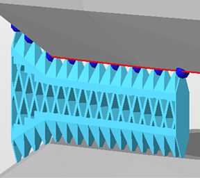
Connection |
Type of connection |
Select from: Strip, Trapoid, Breaking Points, Triangles.
|
|
|
Connection width |
a |
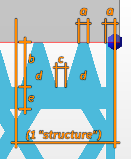 Connection properties |
The width of the vertical strip on the far right can be overridden. See . |
|
Connection height |
b |
|
|
|
Pin distance |
c |
|
|
|
Pins per structure |
d |
|
|
|
Distance connection to structure |
e |
|
|
| Triangles on platform | Adds reinforcing triangle-shaped ribs to the platform connection, perpendicular to the polyline or contour. Not available when Angled Block Support is active. | ||
|
Distance |
The interval between ribs |
||
|
Width |
The width at the base of the ribs. The ribs are always equilateral triangles, so changing the width modifies the height accordingly. |
||
| Platform connection | This section defines the connection between support and platform ground. | ||
|
Connection |
Type of connection. See above for reference. | ||
|
Hatches |
Replicates the lower section of connections in parallel, up to 15 copies in each direction. This creates tapered, pedestal-like reinforcements. Accepts odd numbers up to 31 only, ignores even numbers. | ||
|
Hatch distance |
Distance between replications | ||
| Triangles on platform | Adds reinforcing triangle-shaped struts to the platform connection, perpendicular to the polyline or contour. Not available when Angled Block Support is active. | ||
|
Distance |
The interval between struts | ||
|
Width |
The width at the base of the struts. The struts are always equilateral triangles, so changing the width modifies the height accordingly. | ||