Geometry Check Options
Description: Specifies tolerance values and options for element geometry checks.
Format:

Example:
Set the tolerance for the CQUAD4 element skew angle test to 30.0 degrees and limit element geometry warning/fatal error messages to 100:
GEOMCHECK Q4_SKEW = 30.0, MSGLIMIT = 100
Set the message type to fatal for CQUAD4 element taper tests:
GEOMCHECK Q4_TAPER, MSGLIMIT = FATAL
Request summary table output using default tolerance values:
GEOMCHECK SUMMARY
| Option | Definition | Type | Default |
|---|---|---|---|
| testtype | Element geometry test type: One of the character variables shown in Remark 3. | Character | |
| tol | Tolerance value for the specified testtype. | Real > 0.0 | See Remark 3 |
| n | Maximum number of element geometry warning/fatal error messages. See Remark 4. | Integer | See Remark 4 |
| FATAL | Geometry tests that exceed tolerance values produce fatal error messages. | Character | |
| WARN | Geometry tests that exceed tolerance values produce warning messages. | Character | ✓ |
| SUMMARY | Option to output individual element geometry statistics. See Remark 5. | Character |
Remarks:
- The GEOMCHECK command combines several Geometry Processor Parameters which control element geometry check tolerances, the number and severity of associated warning and fatal error messages, and output of additional tabular summary information. Multiple GEOMCHECK statements may be present.
- Autodesk Nastran performs a number of element checks internally for every analysis. These are done to identify elements that can potentially cause numerical issues, such as singularities. The GEOMCHECK element checks are included to help a user identify elements that will potentially give bad results. Virtually all the distortions that are checked can cause elements to be too stiff (as compared with ideal elements). Additionally, the extrapolation of calculated results from Gauss points to corner nodes is adversely affected in distorted elements. If only centroid output is requested, many of the checks can be relaxed, but highly distorted elements may still be too stiff. The default values for the checks represent limits beyond which the element results may be compromised significantly.

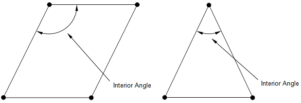
Figure 1. Interior Angle Check.

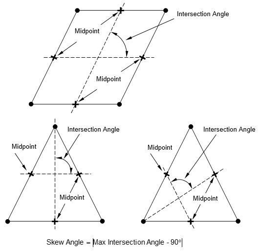
Figure 2. Skew Angle Check.

Figure 3. Taper Ratio Check.

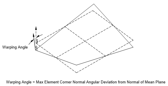
Figure 4. Warping Angle Check.

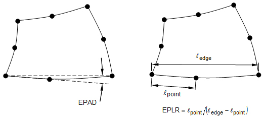
Figure 5. Edge-Point Angular Deviation and Length Ratio Checks.
- The following table lists the
testtype character variable options and the associated model parameter which may also be used to change the default setting.
Testtype Character Variable Equivalent Model Parameter Description Default Value HEX_AR HEXARTOL Hex element aspect ratio. 100.0 HEX_IAMAX HEXFACEMAXIATOL Hex element face maximum interior angle (degrees). 165.0 HEX_IAMIN HEXFACEMINIATOL Hex element face minimum interior angle (degrees). 25.0 HEX_SKEW HEXFACESKEWTOL Hex element face skew angle (degrees). 65.0 HEX_TAPER HEXFACETAPERTOL Hex element face taper ratio. 0.75 HEX_WARP HEXFACEWARPTOL Hex element face warping angle (degrees). 45.0 HEX_EPAD HEXMAXEPADTOL Hex element maximum edge-point angular deviation (degrees). 30.0 HEX_EPLR HEXMINEPLRTOL Hex element minimum edge-point length ratio. 0.5 PENT_IAMAX PENTFACEMAXIATOL Pent element face maximum interior angle (degrees). 165.0 PENT_IAMIN PENTFACEMINIATOL Pent element face minimum interior angle (degrees). 25.0 PENT_SKEW PENTFACESKEWTOL Pent element face skew angle (degrees). 65.0 PENT_TAPER PENTFACETAPERTOL Pent element face taper ratio. 0.75 PENT_WARP PENTFACEWARPTOL Pent element face warping angle (degrees). 45.0 PENT_EPAD PENTMAXEPADTOL Pent element maximum edge-point angular deviation (degrees). 30.0 PENT_EPLR PENTMINEPLRTOL Pent element minimum edge-point length ratio. 0.5 PYR_IAMAX PYRFACEMAXIATOL Pyr element face maximum interior angle (degrees). 165.0 PYR_IAMIN PYRFACEMINIATOL Pyr element face minimum interior angle (degrees). 25.0 PYR_SKEW PYRFACESKEWTOL Pyr element face skew angle (degrees). 65.0 PYR_TAPER PYRFACETAPERTOL Pyr element face taper ratio. 0.75 PYR_WARP PYRFACEWARPTOL Pyr element face warping angle (degrees). 45.0 PYR_EPAD PYRMAXEPADTOL Pyr element maximum edge-point angular deviation (degrees). 30.0 PYR_EPLR PYRMINEPLRTOL Pyr element minimum edge-point length ratio. 0.5 Q4_AR QUADARTOL Quad element aspect ratio. 100.0 Q4_EPAD QUADMAXEPADTOL Quad element maximum edge-point angular deviation (degrees). 30.0 Q4_IAMAX QUADMAXIATOL Quad element maximum interior angle (degrees). 165.0 Q4_EPLR QUADMINEPLRTOL Quad element minimum edge-point length ratio. 0.5 Q4_IAMIN QUADMINIATOL Quad element minimum interior angle (degrees). 25.0 Q4_SKEW QUADSKEWTOL Quad element skew angle (degrees). 65.0 Q4_TAPER QUADTAPERTOL Quad element taper ratio. 0.75 Q4_WARP QUADWARPTOL Quad element warping angle (degrees). 45.0 TET_AR TETARTOL Tet element aspect ratio. 100.0 TET_IAMAX TETFACEMAXIATOL Tet element face maximum interior angle (degrees). 170.0 TET_IAMIN TETFACEMINIATOL Tet element face minimum interior angle (degrees). 5.0 TET_SKEW TETFACESKEWTOL Tet element face skew angle (degrees). 80.0 TET_EPAD TETMAXEPADTOL Tet element maximum edge-point angular deviation (degrees). 30.0 TET_EPLR TETMINEPLRTOL Tet element minimum edge-point length ratio. 0.5 T3_AR TRIARTOL Tri element aspect ratio. 100.0 T3_EPAD TRIMAXEPADTOL Tri element maximum edge-point angular deviation (degrees). 30.0 T3_IAMAX TRIMAXIATOL Tri element maximum interior angle (degrees). 170.0 T3_EPLR TRIMINEPLRTOL Tri element minimum edge-point length ratio. 0.5 T3_IAMIN TRIMINIATOL Tri element minimum interior angle (degrees). 10.0 T3_SKEW TRISKEWTOL Tri element skew angle (degrees). 65.0 Note:- Testtype character variables starting with the characters Q4 are applicable to CQUAD4 and CQUADR elements. Testtype character variables starting with the characters Q8 are applicable to CQUAD8 elements. Testtype character variables starting with the characters T3 are applicable to CTRIA3 and CTRIAR elements. Testtype character variables starting with the characters T6 are applicable to CTRIA6 and CTRIAX6 elements. Testtype character variables names starting with the characters TET are applicable to CTETRA elements. Testtype character variables starting with the characters HEX are applicable to CHEXA elements. Testtype character variables starting with the characters PENT are applicable to CPENTA elements. Testtype character variables starting with the characters PYR are applicable to CPYRA elements.
- Aspect ratio is defined as the ratio of the length of the longest element side to the length of the shortest side. This check looks at all element edges to find the maximum and minimum lengths. For solid elements, edges along all faces are considered. Only element corners are used. Edge nodes of parabolic elements are ignored. Quad and hex elements are often very tolerant of large aspect ratios especially for in-plane loads, hence the large default value. For shear and twisting loads, however, a significantly lower tolerance should be considered. For tri and tet elements, high aspect ratios can result in poor extrapolation of results to corner nodes. It is recommended that a lower tolerance be used for these elements if corner stresses are required.
- Interior angles are defined to be the angles formed by the edges that meet at the corner node of an element. There are four for quadrilateral shapes and three for triangular shapes. A perfect rectangle would have four 90 degree interior angles. An equilateral triangle would have three 60 degree interior angles. Internal angles are evaluated against both a minimum and a maximum tolerance. Like skew, large and small internal angles result in poor element performance, especially as they approach the upper and lower default limits of this check. And internal angle of 180 degrees or more will result in a singular element. An internal angle of zero degrees is also singular.
Skew angle for a quadrilateral element or solid element face is a measure of how much of a parallelogram it is relative to a rectangle. It is defined to be the angle between the lines that join midpoints of the opposite sides of the quadrilateral minus 90 degrees. A rectangle would have a zero skew angle. Skew angle for a triangular element or solid element face is a measure of how close it is in shape relative to an equilateral triangle. Skew angle for the triangular element is defined to be the angle between the lines that join midpoints of two opposite sides relative to the line through their vertex and the midpoint of the remaining side minus 90 degrees. An equilateral triangle would have a zero skew angle. Each vertex of the triangle is examined and the largest skew angle reported. Element accuracy can be sensitive to element skew angle.
- Taper ratio for the quadrilateral element is defined to be the absolute value of (the ratio of the area of the triangle formed at each corner grid point to one half the area of the quadrilateral minus one). The largest of the four ratios is compared against the tolerance value. Note that as the ratio approaches zero, the shape approaches a rectangle. A large taper ratio implies an element that is trapezoid shaped, with a short edge opposite a long edge. High tapers affect the ability of an element to extrapolate Gauss point values to corner nodes accurately.
- The warping angle is the angle formed between the normal vectors located at diagonally opposite corner points. The warping angle is zero when all four corner points are in the same plane. Quad elements are very sensitive to even small amounts of warping and users should keep elements as flat as possible, breaking them up if necessary to prevent warpage.
- The edge point length ratio and edge point interior angle tests are only performed for solid and shell elements when edge node points exist. The length ratio test evaluates the relative position of the edge node point along a straight line connecting the two vertex nodes of that edge. Ideally, the edge point should be located on this line at a point midway between the two end points. The edge point angular deviation is the angle between the lines joining the edge node and the end points. For curved elements, some angular deviation is necessary and expected, but high values will compromise the stiffness of the element.
- The default limit on the number of warning/fatal error messages output for element geometry checks is either 10,000 or the number of lines in the Model Input File, whichever is larger.
- The specification of the SUMMARY character variable is equivalent to PARAM, ELEMGEOMOUT, ON. When ELEMGEOMOUT is set to ON, the following statistics are output to the Model Results Output File for each element:
- Aspect ratio
- Taper ratio
- Skew angle
- Warping angle
- Normalized Jacobian
The data is sorted based on normalized Jacobian determinant, skew angle, and aspect ratio in ascending order for each element type. See Section 5, Parameters, for more information on ELEMGEOMOUT.