Results can be imported and viewed in ParaView or Simulation Utility for Netfabb.
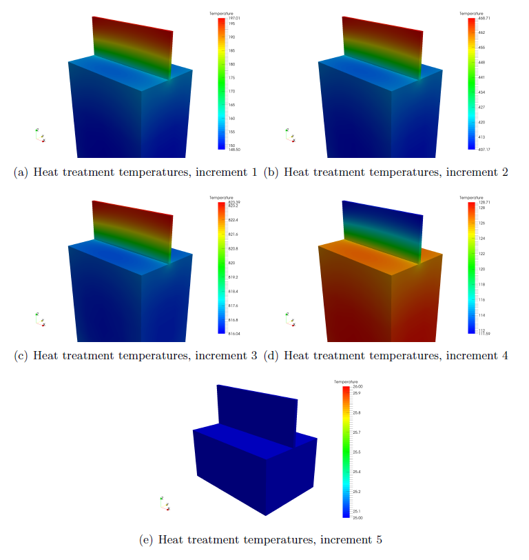
Figure 2 shows the temperatures for different increments in the simulated heat treatment.

Figure 2: Heat treatment temperature results, °C
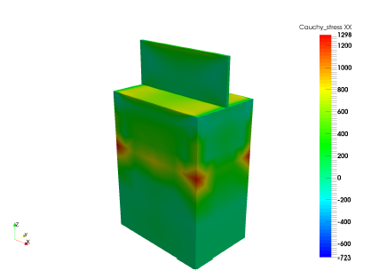
The modeled stresses in the component and build plate after the plasticity model is introduced, but before heat treatment is shown in Figure 3. These are the high residual stresses that make using non-heat-treated AM parts inadvisable.

Figure 3: Modeled stresses prior to heat treatment
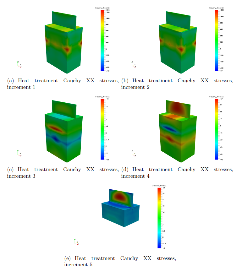
Figure 4 shows the modeled stresses at different increments during the heat treatment simulation.

Figure 4: Heat treatment Cauchy XX stress results
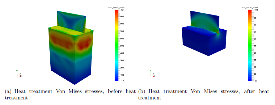
Observe the stresses reduce as the temperatures increase. Then as the heated part is slowly brought back to room temperature, new thermal stresses are introduced. Looking at the Von Mises stresses in Figure 5, the final, room temperature part has peak stresses that are 90% of the peak stresses prior to heat treatment. This achieves the goal of removing 90% of the stresses induced by the LPBF construction process by the means of stress relief heat treatment.

Figure 5: Von Mises stress results before and after heat treatment