Sample files for use with the examples are available from the Downloads page.
Expand the downloaded ZIP archive into a convenient directory from which to run Local Simulation inside the numbered directories.
Problem description
For this example, you will run commands inside directory 07.
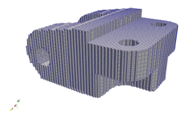
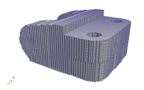
An Inconel 718 bracket geometry with support structures is built in a powder bed system. The layer height is 0.04 mm. The part geometry is imported in the analysis through an STL file, the support structure is imported from an CLI file, and both are automatically meshed within Local Simulation. The build plate is modeled to be 25.4 mm thick using *DDM!. The time to deposit layers is calculated using the *PBDL card. The bottom of the build plate is fixed using the *FSUB card. The *FSUB card will also simulate the release of the build plate from the machine after the deposition process is complete, but before the part is removed from the build plate. The mesh, with and without the support elements, is shown in Figures 1 and 2.

Figure 1: Bracket without supports

Figure 2: Bracket with supports
A time incremental thermal analysis is performed first to compute the temperature history of the part. Layers are activated in groups using *PBPA, and additional time increments are used to model heat conduction into the part. The thermal analysis includes only the part and substrate. Heat loss into the powder is modeled as convection with a value of 25.d-6 W/((mm2)°C) using *CONV.
A time incremental mechanical analysis is performed after the thermal analysis is completed. Similarly to the thermal analysis, layers are activated in groups and the computed temperature distribution from the mechanical analysis is used to compute deformation due to the thermal expansion. These simulations have three additional post-process simulation increments:
- Release of the build plate from the machine
- Removal of the build from the build plate
- Removal of the support structure material from the final build
Two variations of the mechanical analysis are performed: a basic analysis (07_mechanical1.in), and an advanced analysis, which simulates failure at the support-build interface (07_mechanical2.in).