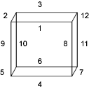
To draw itself, every entity makes calls to graphics primitives such as polylines, circles, and arcs, contained in the AcGi library. Any class derived from AcDbEntity can associate a graphics system (GS) marker with the display vectors it uses to draw itself. Each entity subclass controls where it inserts its GS markers. When a user selects an entity, the GS marker is used to identify which part of the entity was picked.
Solids derived from AcDb3dSolid are composed of vertices, edges, and faces. Each of these elements can be identified by a GS marker. The creator of the entity class decides where GS markers should be inserted, depending on what is most natural for the entity. A box, for example, creates a GS marker for each line used to draw the box. A cylinder creates three GS markers—one for its top, bottom, and outside faces.

An entity is composed of subentities of the following type: vertex, edge, or face. Currently, the only entities that support subentities are bodies, regions, solids, and mlines. Use the getSubentPathsAtGsMarker() function to obtain the paths to the subentities that are associated with a particular GS marker. More than one subentity can be associated with a single marker. In the case of the box, for example, marker 4 identifies the lower front edge of the box. If you ask for the vertices associated with this marker, the two vertices that form the endpoints of this line are returned. If you ask for the edges associated with this marker, one entity—the line—is returned. If you ask for the faces associated with this marker, data for the front face and the bottom face of the box are returned.
AutoCAD's 2D graphics system does not support the use of selection markers with drawing objects whose subentities are on more than one layer. If you use selection markers for a drawing object, all graphics subentities for that object must reside on a single layer. If you must use multiple layers for an object's subentities, do not use selection markers.