This section describes how to create a profile group for the outside diameter of the part:
- Select the color you want to use for this toolpath from the Color Palette:

Using different colors for your toolpaths makes it easier to identify the toolpaths you have programmed when viewing the part geometry, or the solid model, in the PartMaker window.
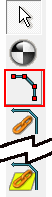
- Click the
New Profile Group button to display the
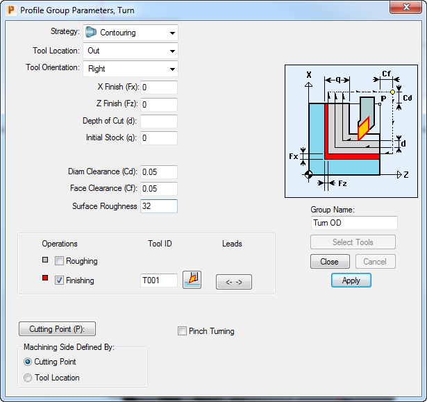
Profile Group Parameters, Turn dialog.

- Complete the Profile Group Parameters, Turn dialog as shown, then click
Close.
- Click the
Define Profile button, so you can specify where the profile goes on the part.
 Note: PartMaker automatically defines profiles for facing and cut-off operations. For other operations, you need to define the profile.
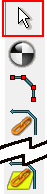
 - Click the
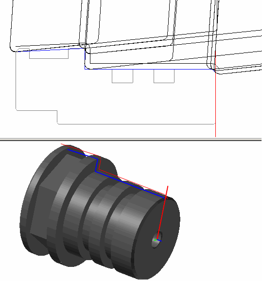
End of an Element Snap Mode button to specify that you want to define the profile by using the part's geometry as 'snap points' for the toolpath:

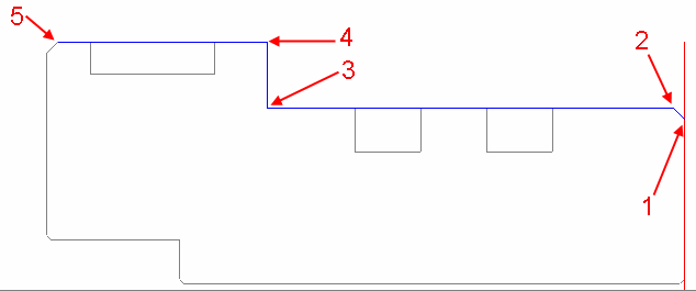
- Click on the part geometry to specify the following snap points in the order shown:
- Click the
Selection button to save the profile.
- To verify the toolpath click the
Verify Work Group Toolpath button, then click
OK on the
Face Window Verification Options dialog.

You can now visualize the toolpath:
- Click the
Hide Every Toolpath button to remove the verification details from the display.
