This section describes how to create a milling toolpath to mill the hexagon on the part.
This section shows you how to create the toolpath using geometry extracted from a 3D solid model. If, however, you want to use geometry from an imported 2D .DXF file instead, select File > Import > DXF File to display the Import DXF File dialog and then select the hex_profile_inch.dxf file from the Getting Started folder of your PartMaker installation. PartMaker displays the 2D geometry in the PartMaker window. You can then follow the steps described in this section.
So far, you have created turning toolpaths in the Front face window. To create a toolpath that uses a different machining function (milling), you need to create a new Face window.
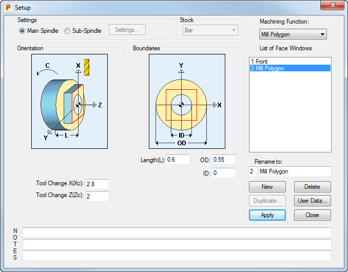
- Select View > Setup and then click New.
- Complete the
Setup dialog as shown, then click
Close to finish.
- Click the
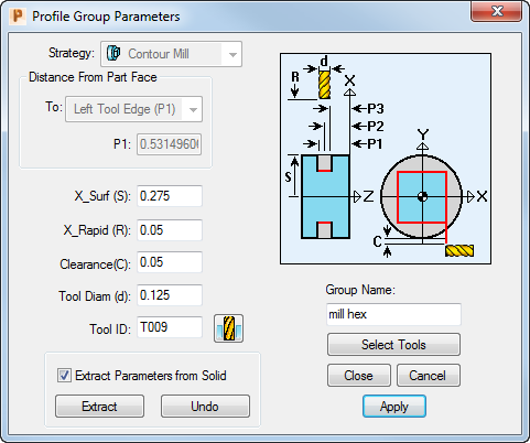
New Profile Group button on the toolbar to display the
Profile Group Parameters dialog.
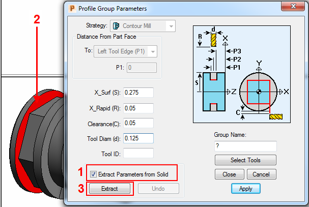
- If you are using the imported 3D solid model, complete the dialog as shown, by selecting the
Extract Parameters From Solid
option, selecting the plane in the Solids window and then clicking
Extract.
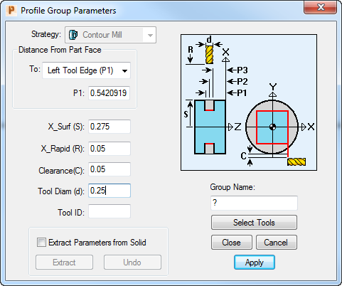
- If you are using the imported
hex_profile_inch.dxf file, complete the dialog as shown:
- If you are using the imported 3D solid model, complete the dialog as shown, by selecting the
Extract Parameters From Solid
option, selecting the plane in the Solids window and then clicking
Extract.
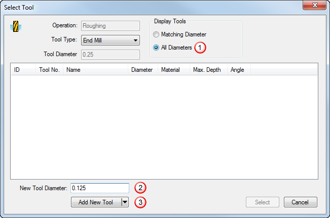
- Click
Select Tools to display the
Select Tool dialog, then select
All Diameters. Notice that only a 0.156" milling cutter is available, which is too wide for the 0.125" hexagonal slot. To specify that you want to create a new 0.125" tool, complete the
New Tool Diameter field as shown below, then click
Add New Tool.
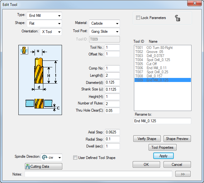
- To create a 0.125" milling tool, complete the
Edit Tool dialog as shown and then click
OK.
- Check the details shown on the
Profile Group Parameters dialog and click
Close. If you are using an:
- imported 3D solid model, continue at Step 7.
- imported 2D .DXF file, continue at Step 8.
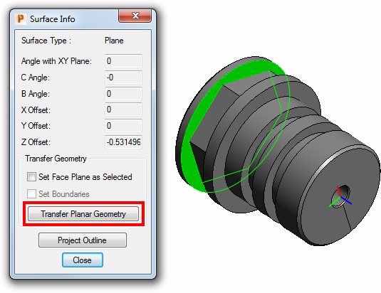
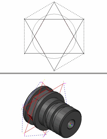
- When using a 3D solid model, you need to transfer the planar geometry from the solid model into the 2D area of the <PRODUCT> window before you can create the profile for that geometry. To transfer the geometry, double-click the surface on the solid model to display the
Surface Info dialog, then click
Transfer Planar Geometry.
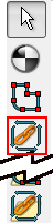
- Click the
Chain Geometry button in the Profile toolbar to specify that you want to create the profile by selecting the end point of the hexagon.
- Click on any of the points on the hexagon to create the profile:

- To verify the profile group, click the
Verify Work Group Toolpath button, then click
OK on the
Face Window Verification Options dialog.

You can now visualize the toolpath:
- Click the
Hide Every Toolpath button to remove the verification details from the display.
